


Chapter 2—Functional Descriptions
Model 330, 340SC and 370SC Service Model 2-13
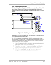
CRT anode voltages are not user controllable. They are fixed at 32KV with a
maximum output of 2.1mA total or 0.7mA per CRT. The anode voltage is the
primary acceleration voltage for the CRT. Other bias voltages (screen grid, G2,
and control grid, G1) are used to control the level of beam current. The anode
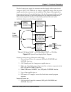
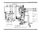
voltage is routed out of the top of the HVPS, into the CRT housing to three (3)
bulkhead connectors. From there, the anode wires on the CRTs route the anode
voltage directly to the CRT. The anode voltages are overvoltage and overcurrent
protected in the event of short circuits or CRT arcing.
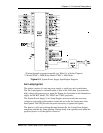
Focus voltage (called Electronic Focus) is a modulated DC voltage. The DC level
is set by the user during initial setup to focus the CRT electron beam. The
Electronic Focus controls are located on the left side of the HVPS (see appropriate
model Operator’s Manual). There are three (one for each color) ¾ turn pots for
adjusting the Electronic Focus. Of the six (6) pots found on the HVPS, the bottom
three (3) are for focus while the top three (3) are for G2 adjustment (Section 3.10).
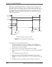
The DC voltage is modulated within the HVPS using the HDFOCUS and
VDFOCUS input signals. VDFOCUS is the vertical dynamic focus signal, which
is a waveform with parabolic shape at the vertical sweep frequency. HDFOCUS is
the horizontal dynamic focus signal. It is a combination of the vertical dynamic
focus signal and a parabolic waveform at the horizontal sweep rate. These two (2)
signals are combined in the HVPS to form a composite dynamic focus signal.
Dynamic focus is necessary to ensure that the CRT electron beam is converged to
a point as the beam sweeps across the CRT face. Since the CRT faceplate is flat,
the raster sweep causes a varying path length for the electron beam. This means
the focus voltage must be varied as the raster is traced. Focus voltage cannot be
conveniently measured during normal operation.
G2 screen grid voltage is a DC voltage that is set by the user. The three (3)
adjustment controls, one for each color, consist of ¾ turn pots and are located on
the left side of the HVPS immediately above the focus controls. This voltage is set
during initial projector setup to adjust the black level on the screen (see
appropriate model Operator’s Manual). The G2 voltage sets the bias on the screen
grid of the CRT and is normally used to set the cutoff level. However, since the
HJT light valve requires a non-zero input to produce a just-cut-off image on the
screen, G2 is set to produce a slightly greater-than-black raster on the CRT. The
G2 is adjustable from 100V to 1400V individually by color. The actual operating
level will be near 1200V. G2 voltage cannot be conveniently measured during
normal operation.
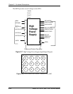
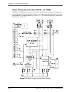
-200V is the supply to the control grid (G1) of the CRTs through the Video
Amplifier Board. This voltage is not user controllable. The -200V is the only
output voltage from the HVPS that goes to the backplane of the projector to be
routed to the Video Amplifier, and uses the rear-most LED of the backplane LED
bar for indication.
-200V is the only convenient means of directly observing whether or not the
HVPS is turned on, either by observing the indicator LED on the backplane, or by
probing the control connector with a voltmeter.