


Chapter 2—Functional Description
Model 330, 340SC and 370SC Service Manual 2-29
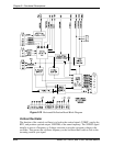
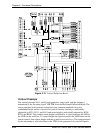
The three (3) horizontal deflection coils (B, G, and R) are driven in parallel by a single
drive circuit and transistor. This is the reason for the inability to remotely control the
three (3) raster widths independently. Since the deflection coils are in parallel, it is
imperative that they all be connected prior to applying sweep voltage—the interlock
circuit ensures this. An output from the Horizontal Power Supply is sent, in series,
through all three (3) yoke connectors. This is part of the bias voltage used to operate the
base drive circuit for the output section. Thus, if any of the yoke connectors is not
connected, the output transistor will not turn on, and no horizontal sweep will be present.
There are two (2) output jumpers on the board, J500 and J501. Their function is to
reverse the direction of the current through the horizontal deflection coils for front and
rear projection. The output cable shall be connected to J501 for rear projection and J500
for front projection (Jumper Settings, Section 3.9).
Horizontal Sweep Failure Detection
Protection of the CRT from spot burns is accomplished by never allowing the CRT to
continue to have beam current when there is no deflection. To this end, the HDB has a
sensing circuit that detects when there is a loss of sweep that may cause CRT damage.
This circuit senses the horizontal flyback voltage and frequency. By sensing both
amplitude and frequency, the projector is able to maintain sweep over the widely varying
input conditions allowed and still protect the CRTs from damage. The flyback signal is
AC coupled and peak detected, then compared with a reference. As long as the flyback
amplitude and frequency are above the minimum allowed, the sweep detection outputs
(HSENSBLU, HSENSGRN, and HSENSRED) are pulled high. These signals are sent to
the VDB for processing.
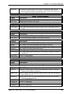
Serial Communication
The HDB uses two (2) separate, interrelated serial data communication systems to
communicate with the SCB; the IIC bus, and a differential, synchronous data bus. The
information transferred over the serial busses is indicated below (I = input to HDB, O =
output from HDB). Also noted is whether the information is transferred over the IIC or
the serial bus. A change in output data generates an interrupt pulse.
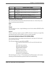
Table 2-6
HDB Serial BUS Information
Bus
I/O
Information
Description
IIC
I
Flyback switch select
Two bits that select one of four flyback switching
times (see detailed description)
IIC
I
Flyback switch pulse
Pulse signal that commands the flyback relays to
switch.
IIC
O
Front/Rear indication
TTL level that indicates whether the projector is
in front screen mode (high) or rear screen
(pulled low).
IIC
O
Floor/Ceiling
indication
TTL level that indicates whether the projector is
in the upright mode (high) or inverted mode
(pulled low).