


Chapter 4—Maintenance
4-22
Model 330. 340SC, 370SC Service Manual
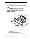
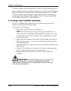
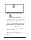
To ensure a proper connection between J11 and P11 follow the procedure below:
Before installing the Horizontal Deflection Board, remove the Vertical Deflection
Board. This allows for a full inspection of the proper connection of J11 and P11.
The P11 connector on the backplane is slightly loose to allow movement for
minor dimensional differences in the position of the J11 connector on the HDB.
Do not tighten connector P11 on the backplane.
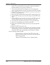
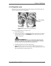
4.12 Image Light Amplifier Assembly
The ILA
®
Assemblies are located in the optics module near the front of the
projector, directly ahead of the relay lenses.
To remove an ILA
®
Assembly:
1.
Remove the front projector cover (Section 4.2).
NOTE:
It may be necessary to remove the left side air baffle cover in
order to gain access to the Blue and Green ILA
®
Assemblies. To remove
the cover, remove the three (3) securing screws and pull the cover loose
from the velcro tabs.
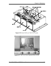
2.
Remove the bias connector from atop the ILA® assembly to be removed.
Mark all bias connectors, or remove one (1) ILA® assembly at a time to
avoid misconnections.
3.
Loosen the hold down clamps on either side of the ILA® assembly (loosen
about 1 turn).
4.
Lift the ILA
®
assembly out of its mount. Use care to avoid getting finger
prints or other contamination on any optical surfaces.
5.
Perform the above steps in the reverse order to replace the ILA®
assembly.
CAUTION!
The
ILA
®
assemblies should be clamped only
enough to eliminate play in the mount. Overtightening can cause
unpredictable performance while undertightening may result in improper
focus and color reproduction.