


Chapter 2—Functional Description
Model 330, 340SC and 370SC Service Manual 2-55
Circuit failure detection.
Beam current sense.
Arc protection.
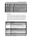
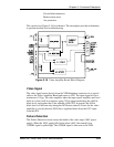
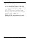
This section uses Figure 2-16 for reference. The description provides information
to perform module-level troubleshooting.
Figure 2-16
Video Amplifier Board, Block Diagram
Video Signal
The video signal comes directly from the VPB backplane connector via a coaxial
cable to the Video Amplifier Board and enters as VIN. The input signal will be a
maximum of 1Vpp. The video amplifier takes the input signal, amplifies and level
shifts it so that it will be a negative-going 75Vpp signal modulating the +84Vdc
black level, and applies this to the cathode of the CRT. In general, the 84Vdc
black level will be seen only during the DC Restore interval. Power for the video
amplifier is a locally derived 100V that is regulated down from the 107V input
from the SPS.
Failure Detection
The Failure Detection circuit senses the health of the video amp's 100V power
supply. When the 100V supply falls below about +64V, the normally low
/VIDOK signal is pulled high. The /VIDOK signal is then sent to the VPB.