


Chapter 2—Functional Description
Model 330, 340SC and 370SC Service Manual 2-35
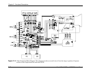
Vertical Amplifiers
The Vertical Amplifiers take the ramp signals generated by the Vertical Preamps and
provide further modification prior to driving the vertical deflection coils. Individual
centering signals, set by the operator and controlled by the SCB are inserted in the
Vertical Output Amps to provide offset for each vertical sweep. The centering of each
individual color can be independently controlled by pressing the POS (Position) button on
the remote control then selecting the desired color. The up and down arrow keys are then
pressed to adjust vertical position. When controlling the position, Green is a master, i.e.
when Green is selected, all three (3) colors move. Red and Blue are independent. After
the centering signal is summed with the ramp signal, the result is amplified to produce the
required amplitude signal to drive the main vertical deflection coils.
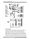
The Vertical Amplifiers output is sent to jumpers for reversing the direction of the
vertical sweep for inverted operation. Jumpers J200, 300, and 400 are used for normal
operation while J201, 301, and 401 are used for inverted operation. A signal is sent to the
SCB indicating which mode of operation the jumpers are specifying.
Sweep Failure Detection
Current through the vertical deflection coil is sensed and that signal used to drive a sweep
indication circuit. There is one (1) circuit for each of Green, Blue, and Red. The sweep
indication circuit combines the vertical current signal with the horizontal flyback signal.
The signals from Green, Blue, and Red are then combined to produce a signal,
/SWEEPOK, that is sent to the VPB and indicates the health of all of the six (6) sweeps.
In addition to the /SWEEPOK signal, there are six (6) LEDs on the VDB which indicate
the presence of the individual sweeps. The LEDs indicating vertical sweep health
(LED200, 300, and 400) are driven by the vertical sweep signal alone. The horizontal
sweep signals affect both of the appropriate color LEDs (e.g.: if the Blue vertical sweep
fails, LED300 would turn off, but if the Blue horizontal sweep fails, LED300 and
LED301 would both turn off).
Side Pincushion and Keystone Correction
This circuit uses the ramp from the Red preamp to generate a variable amplitude
parabolic waveform for use in L/R pincushion correction. The Red ramp is also used to
generate a variable amplitude and polarity ramp for L/R keystone correction. Both the
L/R pincushion and keystone are controlled by the SCB sending a signal over the serial
bus. The operator can control the L/R pincushion by pressing the PIN button on the
remote control. The left and right arrow keys are then used to vary the amount of
pincushion applied. Pressing the KEY button on the remote control can control the L/R
keystone correction. The left and right arrow keys are then used to vary the amount of
keystone correction applied. The two (2) waveforms are then summed.
This signal is then multiplied by HFDBK from the HDB. The resultant signal,
GEOCORR, is sent to the HDB to modulate the horizontal width for side pincushion and
keystone correction.