


Chapter 2—Functional Description
Model 330, 340SC and 370SC Service Manual 2-47
A defective video amp is detected by the state of the /RVIDOK, /GVIDOK, and
/BVIDOK signals arriving from the VABs. A loss of +5V power to the VPB is
detected by observing it internally to this circuit. When any one of the VIDOK
signals goes high or a loss of +5V is detected, action will be taken to shut down
all three (3) CRTs.
Loss of +5V or defective VAB can potentially be more serious than loss of sweep.
Therefore, when one (1) of these conditions occurs, the same action will be taken
as for loss of sweep with the additional action of shutting down the HVPS. This is
done by releasing the /HVEN line allowing the HVPS to pull it high. Turning off
the HVPS is the most effective way of protecting the CRT but is also slowest—
explaining why other actions are taken in conjunction.
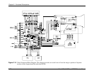
Switch logic is the portion of the circuit that controls what is seen on the screen at
any point at a given time. The SCB sends out signals as the raster is scanned.
These signals are outputs from the on-screen display bit-map. The signals
controlling on-screen video are BONSCRN, RONSCRN, GONSCRN,
VONSCRN, and VIDTEST. The signals are decoded in PALs on the VPB and
result in signals that control the on-screen switch multiplexers to display the test
patterns, text, and video.
Switch logic also takes in the signals from the RTG that control DC restore
(DCRSTR) and blanking (VIDBLANK) and distributes them throughout the VPB
and out to the VAB as the signals CLAMP and BLANKING.
RGB Sensitivity and Threshold Amplifier
Each color of video (R, G, and B) uses an identical circuit.
The video signal is taken from the output of the gamma correction section,
amplified, and sent off the VPB to the VAB via signals RVOUT (TP1), GVOUT
(TP2), and BVOUT (TP3).
The Threshold correction adds an offset to the signal in similar fashion to that of
the brightness control in the Brightness and Contrast Amp. The difference is that
the Threshold correction is, in general, not a pure DC signal, nor does the beam
current limit circuit affect it. Rather, it is a varying signal generated by the System
Controller Board in real time representing the correction necessary to account for
turn-on-point variations across the ILA® Assemblies. The signals from the SCB
are RTHRESH, GTHRESH, and BTHRESH. Also, when the clamp pulse signals
that it is time to do DC restore, the /BPCP signal removes the threshold correction
so that it will be reapplied after DC restore.
Sensitivity correction is applied by varying the gain of the amplifier. Like
threshold correction, the sensitivity correction signal that controls the gain is not,
in general, pure DC nor affected by beam current limit. It is a varying signal
generated by the System Controller Board in real time representing the correction
necessary to account for sensitivity variations across the ILA
®
Assemblies. The
signals for sensitivity correction from the SCB are RSENS, GSENS, and BSENS.