


Chapter 4—Maintenance
4-14
Model 330. 340SC, 370SC Service Manual
4.
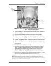
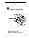
At the rear of the projector, remove the three (3) filter housing screws
(located under the rear lip of the projector base-plate) and remove the filter
housing.
5.
On the left side of the projector, unplug connectors P82 and P83 from the
backplane and move the wiring harness out of the way.
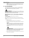
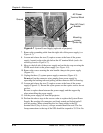
6.
Back all CRTs into the CRT assembly (focus rod screws, at the rear of the
CRT assembly, to the stops—refer to Photo 4-6.
7.
At the base of the electronics module remove the hex screw at each corner
(four [4] screws).
8.
Ensure that all control and input cables are disconnected from the back of
the card cage then tilt the card cage back.
9.
Remove the two (2) hex screws in the base of the electronics module
under the card cage. Tilt the card cage back forward.
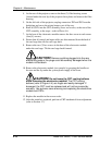
CAUTION!
Remove anything plugged into the rear
electronics jacks or the plugs could be severely damaged when the
module is tilted back.
10.
Remove the electronics module (two people) by grasping the handles at
the rear and the lip under the system power supply in the front.
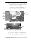
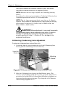
CAUTION!
Do not bump the CRT cooling bellows
while removing the electronics module!
The CRT cooling
bellows (refer to Figure 4-4) are fragile and easily damaged. If
damaged, the CRT must be replaced and will not be covered by
warranty. Use extreme care removing and replacing the electronics
module and CRTs.
11.
Replace the module in the reverse order.
12.
After the module is replaced, perform a CRT mechanical focus adjustment
(refer to Section 3.7).