


Chapter 4—Maintenance
Model 330, 340SC, and 370SC Service Manual
4-21
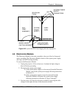
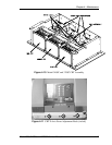
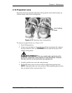
4.11 Card Cage (Printed Circuit Boards)
The card cage is located at the rear of the projector above the CRT housing.
CAUTION!
Printed circuit boards in the electronics module
are susceptible to electrostatic damage. While servicing the projector be
sure to observe electrostatic discharge precautions. Always wear a
conductive wrist strap and ground lead when handling PCBs.
To remove a PCB:
1.
Turn the projector power off at the remote. Wait at least one (1) minute for
the high voltage to bleed off.
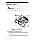
2.
Remove the rear projector cover (see Section 4.2) and toggle the Main
Circuit Breaker to off (see Figure 4-7).
3.
Remove the eight (8) screws securing the electronics module cover and
remove the cover.
4.
Slide the card lock latches toward the center of the card lock and remove
the card lock.
5.
Lift the tabs of the card extractors on the edges of the PCB to unseat a card
from its connector(s).
6.
Lift the PCB from the electronics module.
7.
Replace the PCB in the reverse order.
NOTE:
Each PCB has a dedicated card slot with keyed connector
positions. Observe the connector positions prior to inserting to ensure
proper placement.
CAUTION
!
Before inserting a PCB into the card cage,
ensure there are no bent pins on any connectors. The PCBs may
need to be slightly flexed or jostled in order to properly seat them
into the backplane. Be sure that all connectors on a PCB are
properly aligned with and started into their mating connectors on
the backplane before applying pressure on the PCB or its card
extractor tabs to seat it.
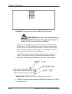
NOTE:
When replacing the horizontal deflection board, the Horizontal
Deflection Board (P/Ns 100566 & 102523) could be damaged if the board
is not seated properly on the Backplane. This problem usually occurs when
the HDB is removed and reinserted after a board failure or when changing
the sweep reversal connector. A failure can occur if connector J11 on the
HDB (located at the far right when viewing from the
component side) does
not connect completely with P11 on the backplane.