


Chapter 3---Service Adjustments
Model 330, 340SC, 370SC Service Manual 3-5
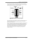
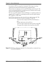
9. View B.
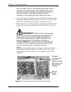
10. Rotate the blue CRT deflection yoke to achieve a level image at the center
of the screen (it should be parallel to the green and red grid center lines).
11. Retighten the yoke clamp so it is secure. Be careful not to over-tighten it.
12. Tilt the electronics module back into place.
13. Replace the allen screw from Step 4 above.
14. Replace the rear cover.
15. After Yoke rotation, re-adjust Geometry, Convergence and CRT
Mechanical focus.
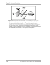
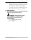
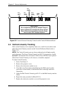
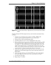
3.3 Vertical Size Tracking
If the R or B vertical size does not match G, adjust the R and B vertical size pots
on the Vertical Deflection Board (see Figure 3-2).
NOTE:
The tracking pots are factory adjusted and should
not
normally need
adjustment. The Green Vertical Size control (R-228) in particular, should
not
need
to
be adjusted unless the Green Yoke or Green CRT has been replaced. If
the Green Vertical Linearity is off, however, it should be adjusted. In this case,
Green should then be matched to Red and Blue.
➨
The Red Vertical Size control is R-428.
➨
The Blue Vertical Size control is R-328.
To adjust the vertical size controls:
1. Press Test 2 to display the White X-hatch pattern.
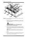
2. Remove the rear projector cover.
3. Remove the eight screws holding the electronics module cover
and remove the cover.
4. From the Convergence menu select #3, CLEAR CONVG AXES.
5. Position R and B over G (using the POS and arrow keys on the
remote–refer to Section 4.9) so that the R and B lines at the
outer edges have the same amount of error.
6. Adjust R328 and R428 so that the Red and Blue vertical sizes
match the Green vertical size.
7. If unable to match Red or Blue to Green, adjust Green to match the
smallest color.
8. Replace the electronics module cover.
9. Replace the rear projector cover.