


Chapter 2—Functional Descriptions
2-28 Model 330. 340SC, and 370SC Service Manual
The first is an input derived from the F to V in the horizontal PLL circuit. This presets the
output of the supply to a voltage that will provide a nominal raster size for the horizontal
frequency applied.
The second input is provided by the SCB via the serial interface. This input allows
control of the raster width by the operator. To control the raster width, the operator
presses the SIZE button on the remote control. Pressing the left and right arrow keys then
controls the width. The three (3) rasters are not remotely controllable on an individual
basis. They can however, be set individually with respect to each other by adjusting the
cores of the variable inductors mounted on the yoke terminal boards (see appropriate
model Operator’s Manual).
Flyback Switching
Flyback switching, necessary to avoid overscan and excessive power consumption over
the wide range of horizontal frequencies covered, is accomplished using relays. When the
input source is changed, the relays are switched to change the response of the resonant
flyback circuit. Since horizontal flyback necessarily causes very high voltages, the relays
must not be switched while under load. When the SCB commands flyback switching to
occur, the switching circuit sends a signal to the GRN Horizontal sweep failure circuit to
turn off the CRT beams. It also sends a signal to the Horizontal Power Supply to turn it
off and shut down the horizontal sweep. The relays are then switched and the sweep and
CRT beams are allowed to return to normal. This sequence of events will occur each time
the input source to the projector changes, regardless of any line rate changes. There are
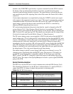
four frequency bands and flyback times that can be set. The frequency ranges and flyback
times are: 6.6uS @ 15-25.1kHz, 4.1uS @ 25-33.1kHz, 2.9uS @ 33-60.1kHz, and 2.4uS
@ 60-90kHz. Flyback switching is not manually controllable by the operator.
Geometric Correction
The HJT Model 330, 340SC and 370SC projectors provide the ability to obtain a
rectangular raster when shooting off-axis in the vertical direction from the screen. This
ability is provided by left/right keystone correction. A geometric correction signal,
GEOCORR, for controlling both the L/R keystone correction and the L/R pincushion
correction is obtained from the Vertical Deflection Board. The GEOCORR signal is a
periodic signal composed of a parabolic summed with a ramp signal, both at the vertical
frequency. This signal is used to vary the width of the horizontal sweep as the vertical
sweep progresses. It does this by modulating the negative voltage applied to the power
transistor, thereby modulating the horizontal width of the raster. The components of
GEOCORR, pincushion correction and keystone correction, are individually controllable
by the operator (see appropriate model Operator’s Manuals).
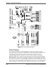
Output Section
The horizontal sync pulse signal produced by the Horizontal PLL is applied to the output
section to control the timing of the horizontal sweep. The output section includes the
power output transistor, base drive circuit, reversing connectors, and interlock circuit.