


Chapter 2—Functional Descriptions
2-64 Model 330. 340SC, and 370SC Service Manual
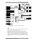
drives the correction amplifiers. The raw (compressed) data is stored in the WCM
while the smooth (expanded) data is stored in the EXM.
When a channel change occurs in the projector, the compressed correction data
that is stored in the WCM is interpolated by the DSP into the expanded form that
is stored in the Expanded Memory.
The compressed data is stored in the WCM in a 33X33 matrix of values
representing the desired correction over the whole screen. For each channel, there
are twelve (12) of these matrices stored in the WCM; one (1) for each color of
each function (R, G, and B for each of X registration, Y registration, Threshold,
and Sensitivity).
Overlay Memory
All display that does not originate from the external source is called Overlay and
includes on-screen text and test patterns. In order to produce overlays, a bit-map
must be generated that can be read out as the raster is being produced by the
projector’s deflection circuits. This bit-map tells what to show on the screen at
any point at any time. The CPU generates the bit-map and stores it in the overlay
memory for readout during raster scanning. When there is no overlay to be
presented, there is nothing but external video to show. That information is also
stored in the overlay memory.
The Overlay Memory is composed of two SRAMs. They are not battery backed
since they store no data that must be held while the projector is not in operation.
The Overlay Memory is used to store the bit-mapped information that describes
the overlay pattern that is seen on the faces of the CRTs, hence on the screen. The
overlay bit-map is 192 fields wide (out of 224) by the total number of raster lines.
Each of these memory locations stores information that determines what will be
displayed at that particular point on the screen. These choices are full bright or
black for each color individually, gray scale for all three (3) colors together, or
external video for all three (3) colors.
Overlay Address Generator
The Overlay Address Generator is used to address the overlay memory in a
manner similar to how the correction address generator addresses the EXM during
both load and readout.
The CPU controls the operation of the Overlay Address Generator while writing
to the overlay memory. During the read times, as with the correction generator,
the overlay address generator uses the /CORRSTRT and /MAPST signals from
the RTG as timing signals. However, the timing clock used is the /HX224 signal.
This is because the generator must run at 224 times the H frequency in order to be
able to generate the 192 addresses required for each line of overlay.
The addresses are generated for 192 clock pulses then the generator pauses. After
the next /CORRSTRT signal, it generates another 192 addresses. This repeats for