


Chapter 2—Functional Descriptions
2-58 Model 330. 340SC, and 370SC Service Manual
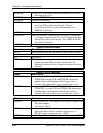
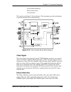
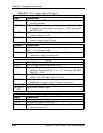
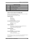
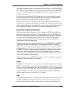
Table 2-11
Video Amplifier Board I/O Signals
Video Processor Board
Input
Description
VIN
COAX input from VPB via the backplane. Video signal of 1V peak-
to-peak maximum.
/ENABLE
TTL level DC signal which controls grid voltages. High causes G2
to be pulled to +15V and G1 to be pulled to -200V shutting off
the CRT beam.
CLAMP
TTL level pulse controlling DC restore. Restores black level of
cathode voltage to +84V.
BLANKING
TTL level signal controlling video blanking. Pulls G1 to 30V below
normal voltage to turn off beam.
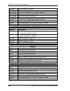
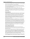
Outputs
Description
BEAM
Positive voltage indicating beam current averaged over several lines.
1mV = 1uA of beam current.
/VIDOK
Indicates health of the +100V cathode supply. Open collector output
opens when supply goes below 64V.
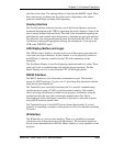
CRTs
Output
Description
FOCUS
Focus voltage directly from HVPS to CRT.
GRID1
Regulated DC voltage to Grid1. Nominally -81V during normal
operation. During blanking, G1 is -111V, and during /ENABLE
high, G1 is -200V.
GRID2
Variable DC voltage to Grid2. G2 voltage is normally 800 to
1200V. When /ENABLE high, G2 is 15V.
CATHODE
DC black level modulated by video signal. DC black level is +84V.
Modulation is negative-going 75V peak-to-peak max.
FILAMENT
6.3V filtered goes to filament.
FILAMENT
RTN
Return from filament supply.
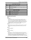
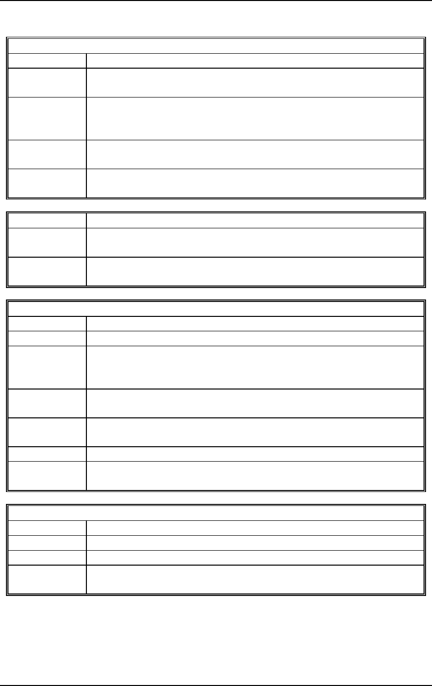
High Voltage Power Supply
Inputs
Description
-200V
Power supply to Grid1 regulator.
FOCUS
Pass-through from HVPS to CRT.
G2
+100V to +1400V supply to Grid2. Passes through G2 pulldown
circuit for protection.