


Chapter 4—Maintenance
Model 330, 340SC, and 370SC Service Manual
4-19
3.
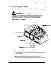
Ensure that all control cables are disconnected from the back of the
cardcage then tilt the card cage back to expose the inside of the CRT
housing.
4.
Unplug and label the five cables connected to the VAB.
5.
Unplug and remove the VAB from the back of the CRT.
CAUTION!
The connector pins on the CRTs are easily
damaged. If damaged, the CRT must be replaced and will not be
covered by warranty. Use extreme care when taking the VAB out of
the CRT housing to avoid damage to the CRT connector pins. In
some cases, it may be necessary to move the CRT all the way
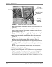
forward (Z axis focus rod, rear of CRT assembly—see to Figure
4-11).
6.
Perform the above steps in the reverse order to replace the VAB.
7.
Perform a CRT Mechanical Focus adjustment (Section 3.7) after replacing
the VAB.
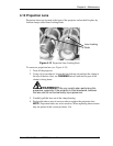
4.9 CRT Yoke
The CRT yoke is located on the CRT neck and is supported by the CRT.
There is one (1) yoke for each CRT.
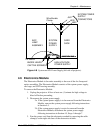
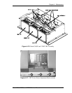
To remove the CRT yoke (see Figure 4-9 or Figure 4-10):
1.
Unplug the projector. Wait at least one (1) minute before proceeding for
the high voltage to bleed off.
2.
Run the CRT all the way forward (Z axis focus rod, rear of CRT
assembly).
3.
Remove the video amplifier board (see Section 4.8).
4.
Loosen the yoke clamp and ensure the yoke is loose on the CRT neck.
5.
Disconnect the yoke cable connector. Slide the yoke assembly off the rear
of the CRT.
CAUTION!
The connector pins on the CRTs are easily
damaged. If damaged, the CRT must be replaced and will not be
covered by warranty. Use extreme care when taking the yoke out of
the CRT housing to avoid damage to the CRT connector pins. In
some cases it may be necessary to use the two other mechanical
focus adjustment rods to tilt the CRT to allow the yoke to be
removed from the CRT neck.
6.
Perform the above steps in the reverse order to replace the yoke assembly.