


Chapter 4—Maintenance
4-12
Model 330. 340SC, 370SC Service Manual
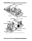
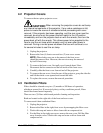
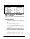
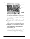
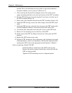
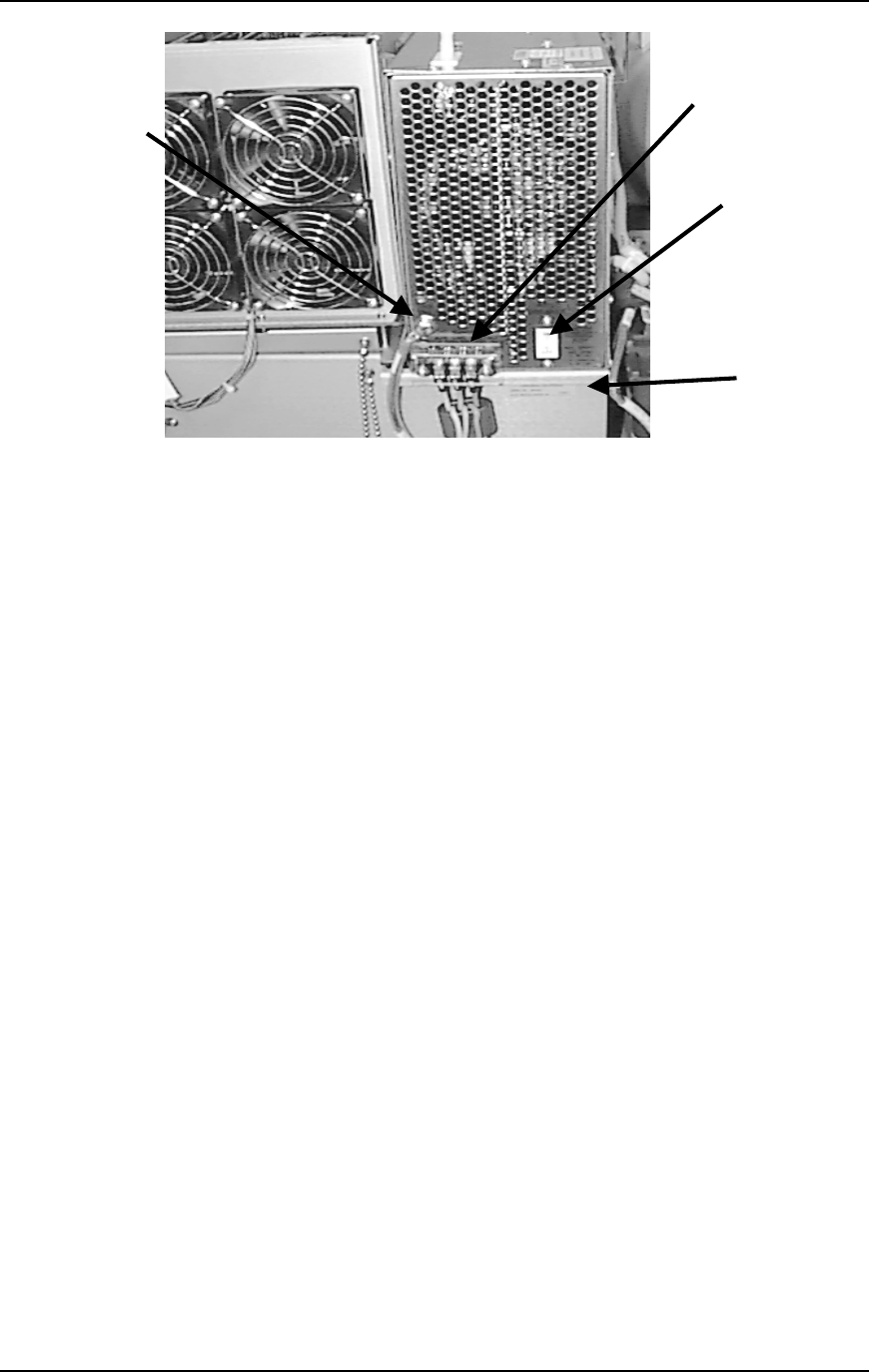
Figure 4-7
System Power Supply (right side of projector)
7.
Remove the grounding cable from the right side of the power supply (see
Figure 4-7).
8.
Loosen and release the two (2) captive screws at the base of the power
supply, located on the right side below the AC terminal block (under the
mounting bracket–Figure 4-7).
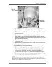
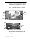
9.
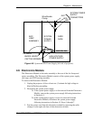
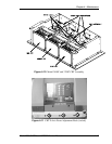
Move to the left side of the power supply and cut the tie wrap securing the
HVPS anode leads to the power supply (see Figure 4-8).
10.
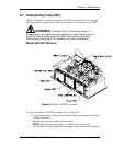
Remove the screw securing the wire bundle clamp to the power supply
(Figure 4-3).
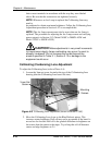
11.
Unplug the three (3) system power supply connectors (Figure 4-3).
Do not pull on the connector wires-unplug from power supply by
squeezing the latching tabs and pulling on the connector shell or housing.
12.
Loosen and release the two (2) captive screws at the base of the power
supply (Figure 4-3). Ensure the nylon spacers on the captive screws do not
get lost.
Be sure to replace them between the power supply and the support lip
when reinstalling the power supply.
13.
Lift the power supply off from the projector.
14.
Perform the above steps in the reverse order to replace the System Power
Supply. Be sure that all connectors are firmly seated and locked and all
pins are mating. When reinstalling the Arc Lamp cables to the DC
terminal block (Step 4 above), a torque wrench should be used. The Arc
Lamp connections to the top of the SPS should be torqued to 25-30 in. lbs.
Main AC Circuit
Breaker
Ground
Mounting
screws
(under lip)
AC Power
Terminal Block