


C-7
Appendix C
Host Computer Interface
C.2.Serial (RS-232C/RS-422A) Interface
RS-232C interface
Interface Signals
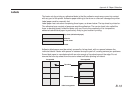
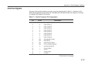
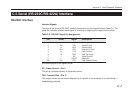
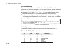
The pins of the printer’s RS-232C interface connector carry the signals listed in Table C.2. The
table also indicates whether each signal is incoming or outgoing with respect to the printer.
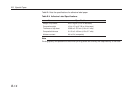
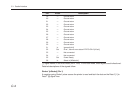
Table C.2. RS-232C Signal Pin Assignments
Pin In/out Signal Description
1 — FG Frame ground
2 Out TXD Transmit Data
3 In RXD Receive Data
4 Out RTS Request To Send
5 In CTS Clear To Send
6 In DSR Data Set Ready
7 — SG Signal Ground
11 — +5V DC Reserved
20 Out DTR Data Terminal Ready
Brief descriptions of the signals follow.
FG - Frame Ground - (Pin 1)
This pin is connected directly to the printer frame.
TXD - Transmit Data - (Pin 2)
This output carries asynchronous data sent by the printer to the computer. It is used mainly in
handshaking protocols.