4 - 19 4 - 19
MELSEC-Q
4 SETTINGS AND PROCEDURES PRIOR TO OPERATION
In linked operation, all data received from one of the two interfaces is
transmitted from the other interface. In this case, exclusive control of the
received data is necessary when data is communicated using the non-
procedure protocol since all the connected stations receive the data.
When data communication is performed using the MC protocol, only
the Q series C24 having the station number designated in the
message performs the process designated by the command.
Furthermore, when data communication is performed using QnA
compatible 2C/3C/4C frames of the MC protocol, the header
information for linked operation is added to messages directed to
other stations linked by multidrop connection.
a
Processing performed by the Q series C24 connected to an
external device
• The header information is added to the command messages
received from the external device that are directed to other
stations and sends them to the stations through the other
interface.
• The header information is deleted from the response
messages received from other stations and sends them to the
external device using the other interface.
(The header information is also sent during m:n connection.)
b
Operation of the accessed station
The accessed station processes the request contained in the
command message, adds the header information to a response
message, and sends it using the interface that received the
command message.
REMARK
The following describes the header information that is added by the Q series C24 to
a message in linked operation.
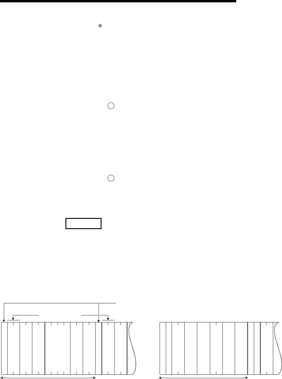
1) When communicating with ASCII code (formats 1 to 4)
The following 13/15 character header information is added immediately before
the control code (ENQ/STX/ACK/NAK) at the start of each message (13
characters for formats 1, 3 and 4; 15 characters for format 2).
2) When communicating in binary mode (format 5)
The following 10 byte header information is added immediately before the
control code (DLE + STX) at the start of each message.
(In ASCII code communication)
Existence in format 2
"STX" in format 3
(In binary code communication)
Header information (10 byte)Header information (13/15 characters)
E
N
Q
E
N
Q
D
L
E
S
T
X
D
L
E
S
T
X
HL HL HL H L HL HL HL HL LH LH LH
--
Block No.
Frame ID No. for link
Module I/O No. for
link station
Module station No.
for link station
System data
Station No.
Block No.
Frame ID No.
System data
Frame ID No. for link
Station No.
Module I/O No. for
link station
Module station No.
for link station
System data
No. of data bytes


