


7 - 11 7 - 11
MELSEC-Q
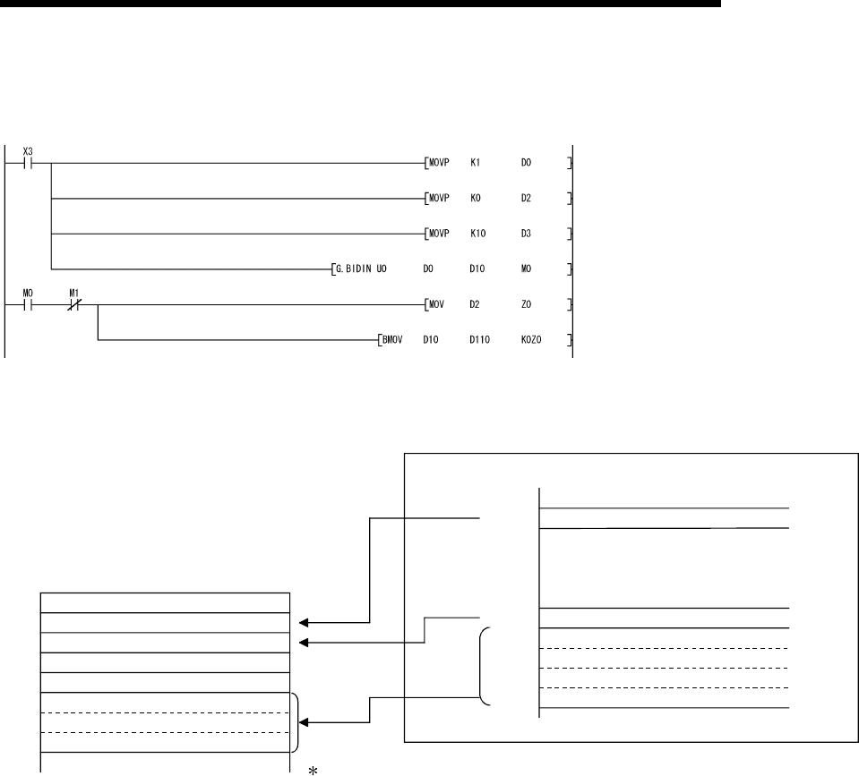
7 DATA COMMUNICATIONS USING BIDIRECTIONAL PROTOCOL
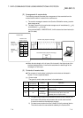
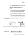
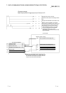
(Program example)
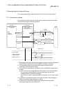
When Q series C24 I/O signals are from X/Y00 to X/Y1F:
Clear the receive data count storage device
to 0.
Designate the allowable receive data count.
•
The reading of received data is performed
by the PLC CPU.
Designate the receive channel.
•
After the BIDIN instruction is executed,
the user designated read completion
signal (M0) comes on for 1 scan.
With the normal completion, the receive
data within the allowable receive data count
(user designated) is read from the receive
data storage area in the buffer memory.
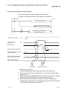
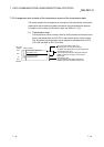
Interface number
Reception result
Receive data count
Allowable receive data count
Receive data
Receive data
D 0
D 1
D 2
D 3
D10
D m
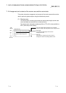
When the received data count is larger than the
allowable received data count, only the data up to
the allowable received data count will be stored
and the excess data will be discarded.
Buffer memory
Data reception result storage area
Receive data count storage area
Receive data storage area
Address
258
H
600
H
601
H
7FF
H
For normal completion
(1)
(0)
(n)
(10)
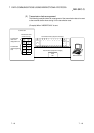
Q series C24
to
to
to