


7 - 5 7 - 5
MELSEC-Q
7 DATA COMMUNICATIONS USING BIDIRECTIONAL PROTOCOL
POINT
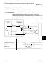
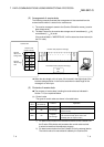
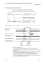
(1) The position and size of the receive area in the buffer memory can be changed
with GX Configurator-SC in accordance with the specifications of the external
device and the received data length. (See Sections 8.4.5 and 8.4.7.)
(a) When changing the position and size of the receive area in the buffer
memory with GX Configurator-SC, specify as follows:
1) Receive buffer memory head address designation
Designate the starting address for the area to be used as the receive
area in the user definable area of the buffer memory (address: 400
H
to
1AFF
H
, 2600
H
to 3FFF
H
).
2) Receive buffer memory length designation
Designate by addresses the length of the area (0001
H
to 1A00
H
) to be
used as the receive area in the user definable area of the buffer
memory (address: 400
H
to 1AFF
H
, 2600
H
to 3FFF
H
).
(b) If the following functions are also used when the position and size of the
receive area in the buffer memory are changed, make sure that the
addresses of the receive area do not overlap with those for the buffer
memory that stores the transmission and reception data to be used by
these functions.
1) MC protocol buffer memory read/write function
2) MC protocol on-demand function
3) Non procedure protocol transmission/receive function
4) Bidirectional protocol transmission/receive function
5) Communication data monitoring function
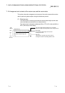
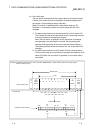
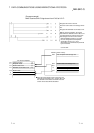
(2) When sending data to the Q series C24 from the external device, one of the
following two adjustments should be made so that the relationship shown
below is maintained.
1) Reduce the send data size.
2) Increase the receive area.
(Receive data storage area) ≥ (Size of data portion sent from the external device)