


10 - 14 10 - 14
MELSEC-Q
10 TROUBLESHOOTING
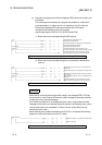
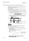
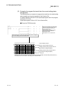
(2) Example of a program that reads from the current setting status
storage area
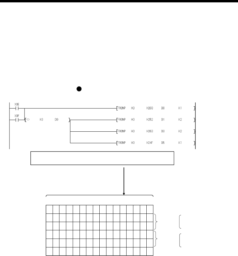
The following shows an example of a program that reads from the switch setting
status storage area for current operation of the Q series C24.
For details regarding XE and XF of the input/output signals used in the program,
see Section 10.1.2 (3).
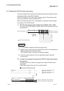
(input/output signals X/Y00 to X/Y1F of the Q series C24)
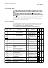
Example of FROM instruction
Reads error description from address 203
H
.
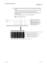
After checking error codes and changed setting values, designate
the correct setting values and switch mode.
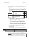
b15b14b13b12b11b10 b9 b8 b7 b6 b5 b4 b3 b2 b1 b0
Error description (2: Communication rate error)
D0
D1
CH1 side
D2
D3
D4
Setting communication protocol number 6
(transmission setting description)
CH2 side
Setting communication protocol number 1
(transmission setting description)
While the CH1 side is set to the non procedure protocol and the CH2 side is set to the MC protocol (format 1),
this indicates the communication rate setting error on the CH1 side.
0000000000000110
0000111100001010
0000000000000001
0000010101101010
0000000000000010
00000 00 00 000 00 01
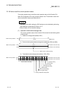
Communication protocol
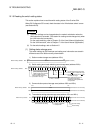
Reads CH1 side communication protocol
status and transmission status from
addresses 252
H
to 253
H
.
Reads CH2 side communication protocol
status and transmission status from
addresses 262
H
to 263
H
.
Reads station No. from address 24F
H
.
D5
Station No. 1 being set.