10 - 37 10 - 37
MELSEC-Q
10 TROUBLESHOOTING
10.3.10 Troubleshooting when communication error "CH1 ERR.", "CH2 ERR." generate
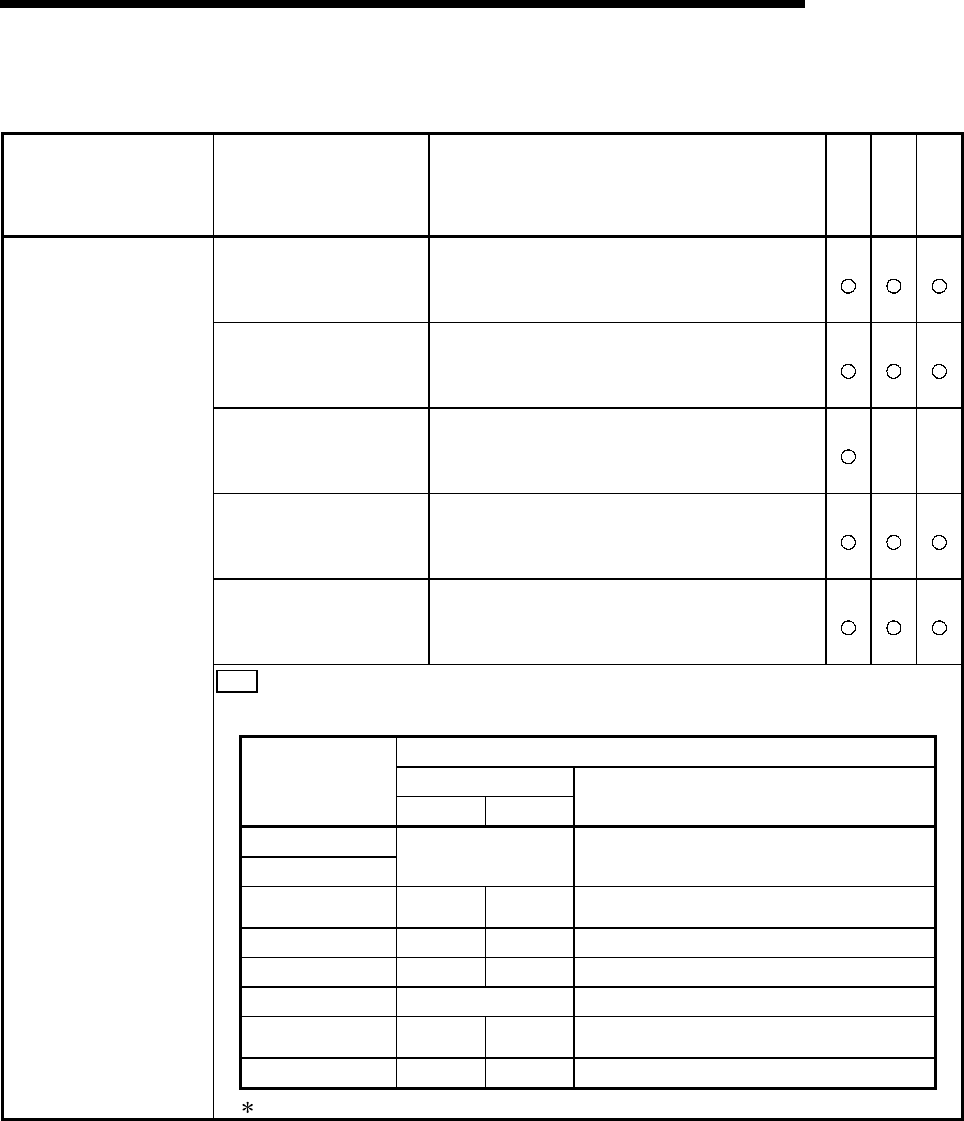
Symptom Cause Corrective action MC
Bidirectional
Non
procedure
• There is an error in the
communication protocol
or transmission setting.
• Read the error code from the buffer memory
and check the error contents and change the
switch setting to the correct setting.
• There is an error in the
on-line mode switching
designation.
• Read the error code from the buffer memory
and check the error contents and correct the
designation contents.
• On-demand execution
generated an error.
• Read the error code from the buffer memory
and check the error contents and correct the
designation contents.
• The Q series C24
detected an error while
transmitting data.
• Read the error code from the buffer memory
and take the corrective action corresponding to
the error contents.
• The Q series C24
detected an error while
receiving data.
• Read the error code from the buffer memory
and take the corrective action corresponding to
the error contents.
Note
• When the "ERR." LED is turned on, the error code is stored to the following buffer memory.
Error code storage buffer memory
AddressError cause
CH1 CH2
Name
Switch setting error
Mode switching error
203
H Switch setting error, mode switching error storage area
On-demand execution
error
256
H
266
H
On-demand execution result storage area
Data transmission error 257H 267H Data transmission result storage area
Data receive error 258H 268H Data receive result storage area
Modern function error 221
H
Modern function error code storage area
MC protocol
transmission error
025A
H
026A
H
MC protocol transmission error code
Monitoring device error 2205
H
2305
H
PLC CPU monitoring function execution result
• "ERR." LED turned on.
See Section 10.2 for a detailed description of the error codes.


