


10 - 9 10 - 9
MELSEC-Q
10 TROUBLESHOOTING
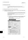
10.1.3 Reading the RS-232 control signal status
This section explains how to read the control signal status stored in the buffer memory
during communication using RS-232 interface.
When GX Configurator-SC is used, check the status using the "Transmission control
and others monitor/test" screen (see Section 8.6.3).
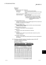
When a transmission problem occurs, read operation is executed to check the signal
on/off status of the RS-232 interface.
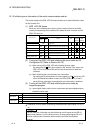
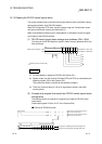
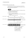
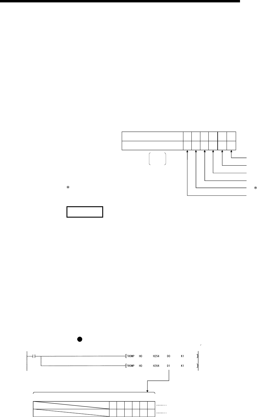
(1) RS-232 control signal status storage area (address: 254
H
, 264
H
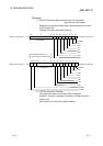
)
The status of the RS-232 signals is stored in buffer memory addresses 254
H
and
264
H
as follows:
1 : ON
0 : OFF
b0b1b2b3b4
to
Buffer memory address
264
H
0
0
(Information on CH1 side)
(Information on CH2 side)
1/0
1/0
1/01/01/0
1/01/01/0
b15 b5b6
1/0
1/0
254
H
System area for QJ71C24 (-R2)
RS
DSR
DTR
CD
RI
CS
1/0
1/0
REMARK
(1) For more details on signals for RS-232, see Section 3.2.1.
(2) Signals output from the Q series C24 side (RTS and DTR) are controlled by the
operating system (OS) of the Q series C24.
They cannot be directly controlled by the sequence program.
(3) There is a maximum delay of 100 ms in signal status stored in the buffer
memory above.
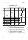
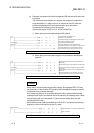
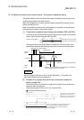
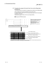
(2) Example of a program that reads from RS-232 control signal status
storage area
The following shows an example of a program that reads the RS-232 control
signal status.
(input/output signals X/Y00 to X/Y1F of the Q series C24)
Example of FROM instruction
b15
to
b4 b3 b2 b1 b0
0
1
1
1
1
1
1
0
D0
D1
CD signal: ON, DTR signal: ON, DSR signal: ON
DTR signal: ON, DSR signal: ON, RTS signal: ON
0
0
b5
0
0
b6
Reads the status of RS-232 control signal on
the CH1 side from address 254
H
.
Reads the status of RS-232 control signal on
the CH2 side from address 264
H
.
Read command