4 - 31 4 - 31
MELSEC-Q
4 SETTINGS AND PROCEDURES PRIOR TO OPERATION
(Procedure 5) Ending the loopback test
Perform the following procedure according to the function used, and start data
communication.
• Set the switch settings with GX Developer according to the procedure specified in
Section 4.5.2.
• Turn on the power to the station on which the Q series C24 is installed.
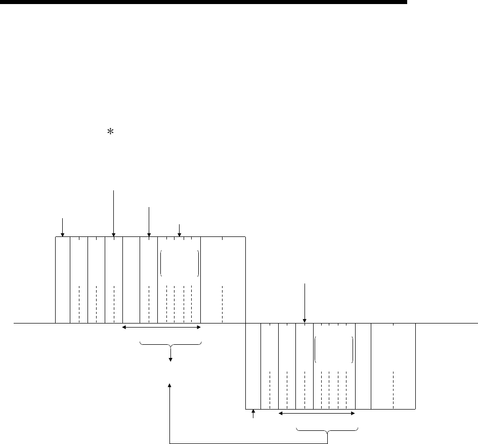
An example of control procedure when the TT command is used in the loopback
test mentioned in Procedure 3.
(Station number: 00, sum check code: Yes)
PLC CPU side
(Example)
(Data name)
External
device side
Header data sent
by the external device
TT (ACPU common command)
Two characters (hexadecimal) … Designate the number of characters (1 to 254) of return data to be
sent immediately afterward.
Designate with a text string consisting of "0" to "9" and "A" to "F" (capital letter)
(In case of format 1)
Two characters (hexadecimal)
Character A part
Becomes the
same data
Header data to be sent by
the PLC CPU
Character B part
S
T
X
E
T
X
02
H
30
H
30
H
46
H
46
H
30
H
35
H
41
H
42
H
43
H
44
H
45
H
03
H
41
H
33
H
HL
00
HL
FF
HL
05
AB CDE
H
L
A
3
E
N
Q
41
H
42
H
43
H
44
H
30
H
37
H
38
H
AB CDE
H
L
7
8
35
H
45
H
30
H
54
H
54
H
46
H
46
H
30
H
30
H
05
H
H
L
0
0
H
L
F
F
T
T0
0
5
H
L
Station No.
PC No.
Command
Message wait
Character length
Loopback data
data with the
length given
by Character
length
Sum check
code
Station No.
PC No.
Character length
Loopback data
data with the
length given
by Character
length
Sum check
code
(Example)
(Data name)


