6 - 11 6 - 11
MELSEC-Q
6 DATA COMMUNICATION USING THE NON PROCEDURE PROTOCOL
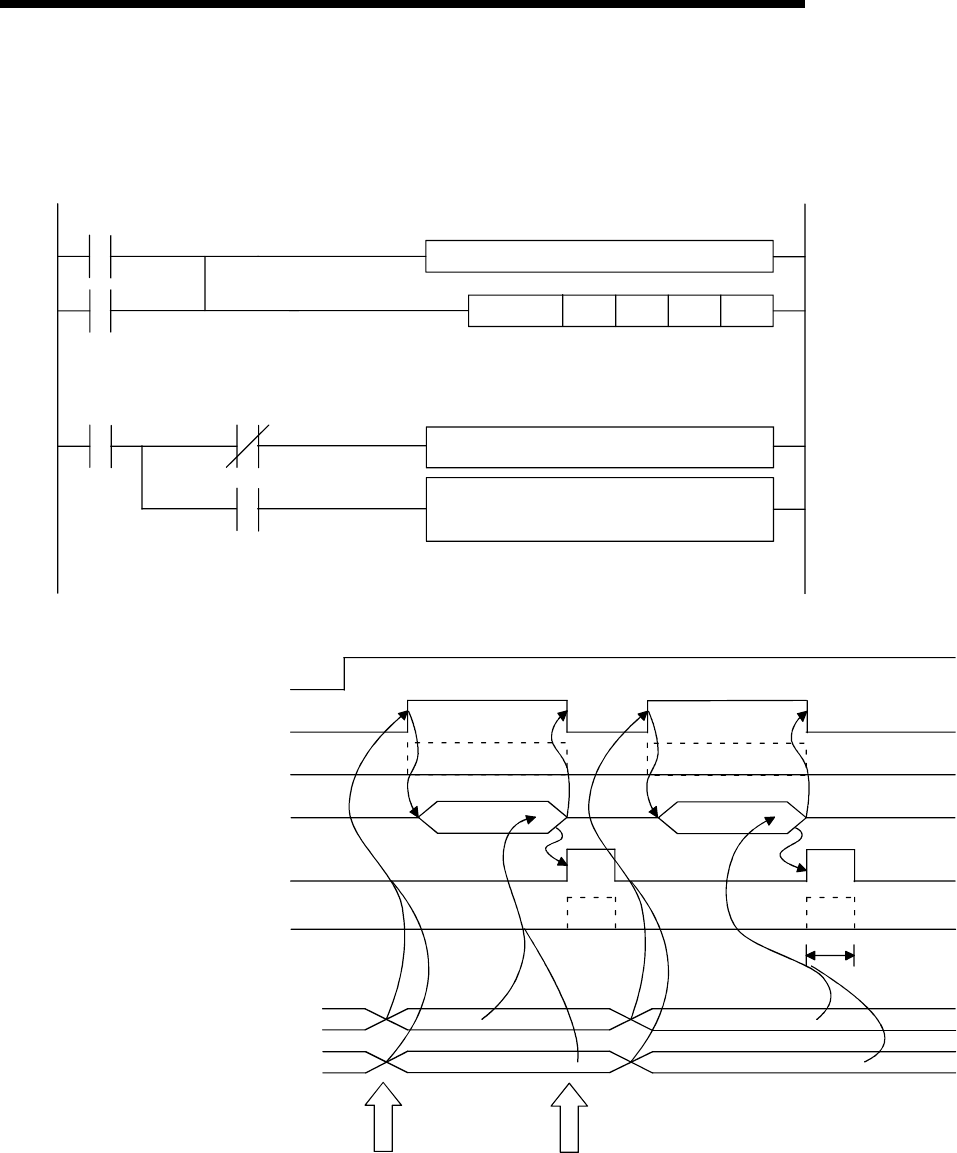
6.1.3 Sequence program for data reception
This section explains the sequence program for data reception.
For details on the INPUT instruction for data reception, see Chapter 9.
X3
Read request
X4
Abnormal
detection
G.INPUTUnD0D10M0
M0
M1
M1
Create control data from D0
Processing for normal completion
(receive data is stored)
Processing for abnormal completion
(Reading and discarding received data,
resent request, etc.
(CH1 side)
(CH1 side)
ON during abnormal
reception detection
Q series C24 ready signal
Reception data read request
signal
Reception abnormal detection
signal
INPUT instruction
INPUT instruction complete
device
INPUT instruction complete
device +1
(Normal completion/abnormal completion)
Received data count storage area
(Buffer memory address: 600
H
)
Received data storage area
(Buffer memory address: 601
H
to)
(X1E)
(X3)
(X4)
(M0)
(M1)
1)
2)
3)
4)
4)
INPUT INPUT
mn
1
Receive data 1
Receive data 2
Data reception-1 Data reception-2
1 scan
Data reception
2)
3)
ON during abnormal
reception detection
1) Start the self-station PLC.
The values specified with GX Developer are stored in the Q series C24.
2) When the amount of data specified by the received data count or data containing
the receive complete code is received from the external device, the reception data
read request signal turns ON.
3) After the control data for the INPUT instruction is stored in the device, the
sequence program executes the INPUT instruction and reads the receive data.


