


6 - 27 6 - 27
MELSEC-Q
6 DATA COMMUNICATION USING THE NON PROCEDURE PROTOCOL
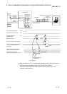
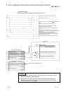
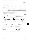
(Program example)
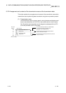
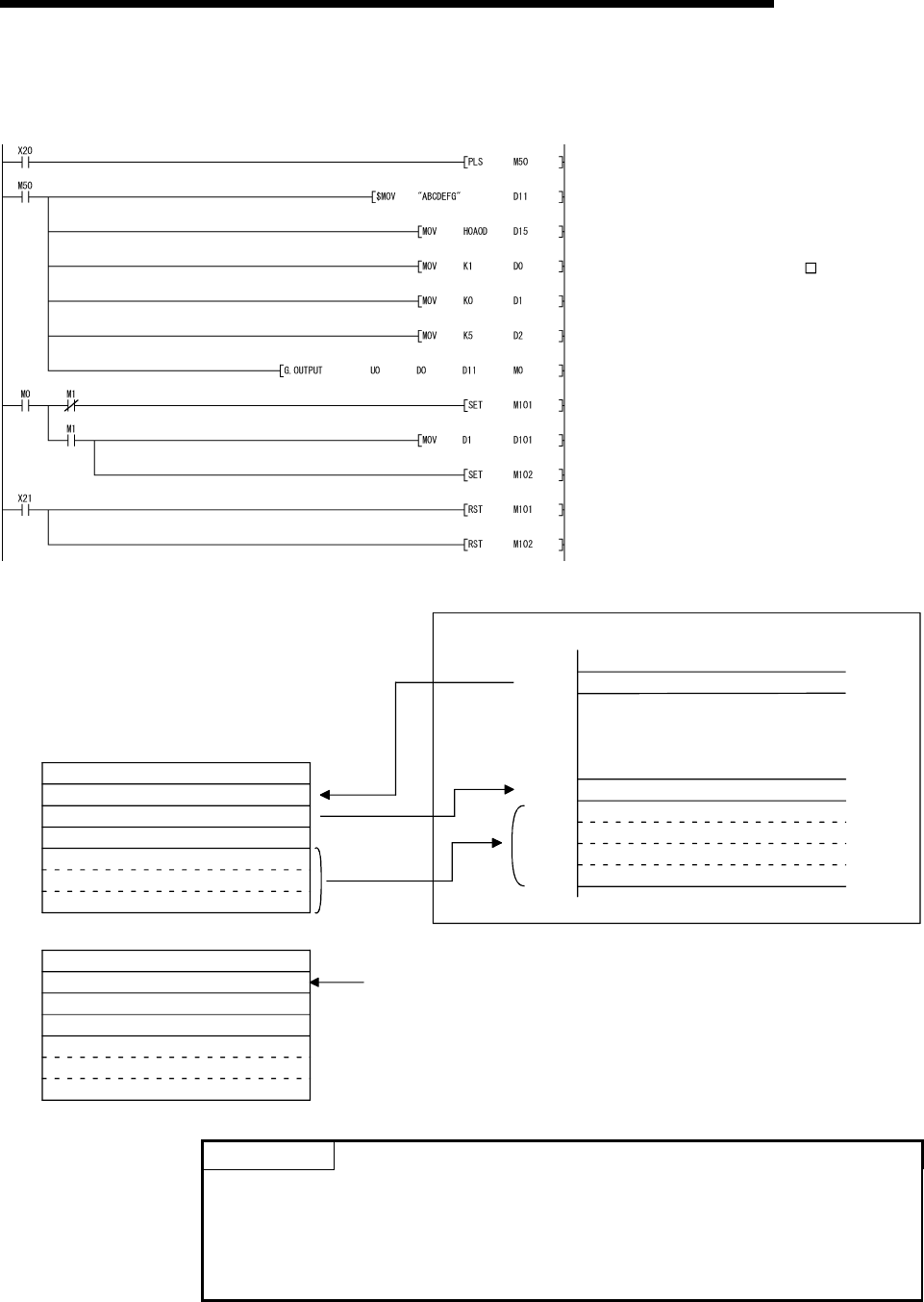
When Q series C24 I/O signals are from X/Y00 to X/Y1F:
The transmission command is converted into pulse.
The transmission data stored in the designated device
is sent.
Designate the number of the interface(CH ) that will send the
data.
Designate the transmission data count in word units.
(Designate K10 when the unit is bytes.)
Clear the transmission result storage device to 0.
Transmission data is stored.
After the OUTPUT instruction is executed, the user
designated transmission complete signal (M0) turns ON
for one scan.
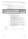
Storing the transmission data and writing the
transmission data count in the buffer memory, and
issuing a transmission request to the Q series C24 are
all executed by the PLC CPU.
The completion flag is reset by an external command.
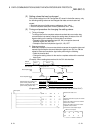
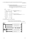
Interface number
Transmission result
Transmission data count
(0001
H
)
(0000
H
)
D 0
D 1
D 2
D11
D15
From buffer memory (address 257
H
)
Buffer memory
Data transmission result storage area
Transmission data count designation area
Transmission data designation area
Address
257
H
400
H
401
H
5FF
H
(4241
H
)
(0A0D
H
)
(0001
H
)D 0
D 1
D 2
D11
D15
(4241
H
)
(0A0D
H
)
Q series C24
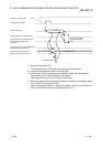
For normal completion
(0005
H
)
(0005
H
)
For abnormal completion
Interface number
Transmission result
Transmission data count
to
to
to
to
to
(other than 0000
H
)
Transmission data
Transmission data
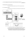
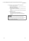
POINT
(1) The SPBUSY instruction is used to read the execution status when using a
dedicated instruction. (See Chapter 9.)
(2) More than one OUTPUT instruction cannot be executed simultaneously.
Execute the next OUTPUT instruction only after the execution of the first
OUTPUT instruction is completed.