4 - 17 4 - 17
MELSEC-Q
4 SETTINGS AND PROCEDURES PRIOR TO OPERATION
(d) Station number setting (switch 5 (common for both CH1 and CH2 sides))
• This setting is for communication using the MC protocol.
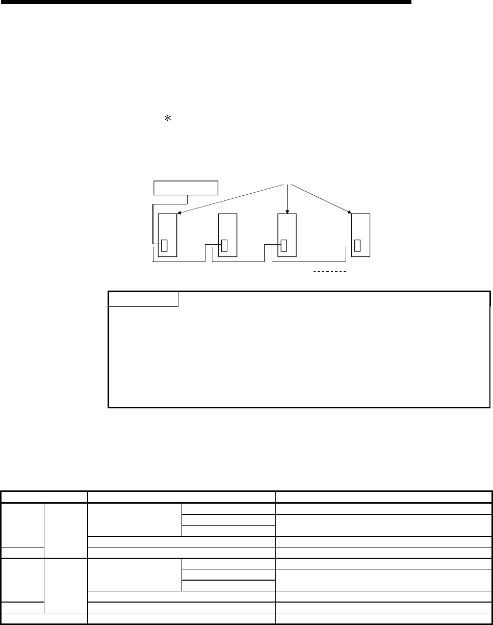
• When several the Q series C24s are connected on the same line with
multidrop connection, set the station number designated in the data items
of the transmission frame in each external device to 0 to 31 (0
H
to 1F
H
).
This number designates which external device is to be communicated
with the Q series C24.
• Set the station number to 0 when the system configuration of the external
device and the PLC CPU is 1:1.
External device
Station 0 Station 1 Station 2 Station 31
Q series C24
POINT
If the communication of data with external device is to be started, check the
specifications of the functions to be used and then make the settings and connect
the cables.
Make the following switch settings from the GX Developer if there is to be no
communication (if the cables are not to be connected) at the interface.
• Communication protocol setting
: Set between 0
H
and 7
H
.
• Transmission setting, communication rate setting: Set all to OFF.
(2) The setting and data flow in linked operation
(a) Set the related switches as follows when two Q series C24 interfaces are in
linked operation.
Switch number Settings Setting value
Operation setting b0 = OFF
Data bit settingTransmission setting
:
Set each switch on both CH1 and CH2 sides to
the same specification.
Switch 1
Communication rate setting Match the external device.
Switch 2
CH1 side
Communication protocol setting 8
Operation setting b0 = ON
Data bit settingTransmission setting
:
Set each switch on both CH1 and CH2 sides to
the same specification.
Switch 3
Communication rate setting Match the external device.
Switch 4
CH2 side
Communication protocol setting 0 to 7
Switch 5 Station number setting Set according to (d) of (1)


