


4 - 28 4 - 28
MELSEC-Q
4 SETTINGS AND PROCEDURES PRIOR TO OPERATION
4.7.2 Individual station loopback test
The individual station loopback test checks the operation of the communication
function of the Q series C24.
Follow the procedure below to perform an individual station loopback test.
(Procedure 1) Connecting cable
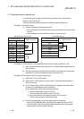
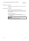
(1) Connect cables to two interfaces as follows.
• Connect cables to the RS-232 interface within the connector and install it to the
interface.
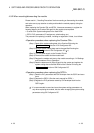
• Connect cables to the RS-422/485 interface on a terminal block.
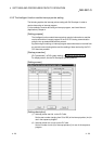
RS-232 interface (D-Sub 9 pin) RS-422/485 interface
Q series C24 side Q series C24 side
Signal name Pin number
Cable connection
Signal name
Cable connection
CD 1 SDA
RD (RXD) 2 SDB
SD (TXD) 3 RDA
ER (DTR) 4 RDB
SG 5 SG
DR (DSR) 6 FG
RS (RTS) 7 FG
CS (CTS) 8
RI (CI) 9
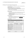
(Procedure 2) Communication protocol setting and transmission setting (see Section 4.5.2)
(1) Set the communication protocol setting to F
H
(individual station loopback test) for
both interfaces.
(2) Set each transmission setting of the two interfaces according to the transmission
specification for data communication with an external device.
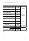
(Procedure 3) Performing the individual station loopback test
(1) Set the PLC CPU to STOP status.
(2) Restart the PLC CPU station or reset the CPU. The test starts automatically in
about one second.
(3) For the Q series C24, perform the following tests in sequence and repeat them
(one test cycle takes approximately one second).
End testing when all test results become abnormal.
1) Check communication with the PLC CPU
Read and check the model type of the PLC CPU.
2) Check transmission and reception functions of the interface
Perform communication while changing data.
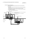
(4) The LED corresponding to a test item flashes when the test starts.
• The CH1 NEU LEDs flash when checking communication with the PLC CPU.
• The SD and RD LEDs of the interface being tested flash when checking the
communication functions of each interface.