3 - 22 3 - 22
MELSEC-Q
3 SPECIFICATIONS
Address
Decimal (Hex)
Applicable
protocol
CH1 CH2
Application Name
Initial
value
MC Non Bi
Registration
allowed/not
allowed
Reference
section
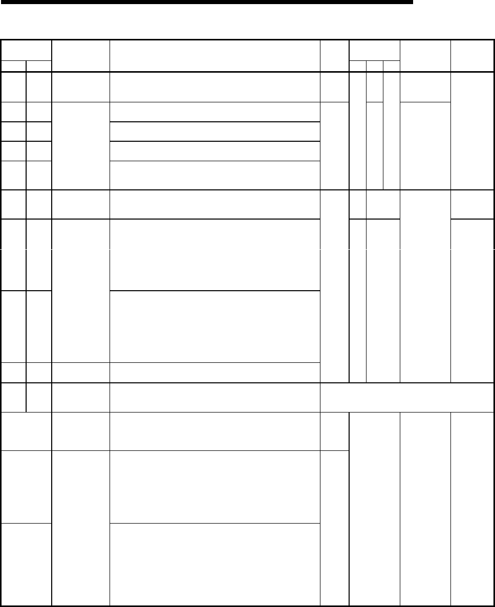
User frame being transmitted
182
(B6H
)
342
(156
H
)
User frame being
transmitted
0 : Not send
1 to 100: User frame being transmitted (nth)
0 R Not allowed
CR/LF output designation
183
(B7
H
)
343
(157
H
)
0: Do not send. 1: Send.
Output head pointer designation
184
(B8
H
)
344
(158
H
)
0: No designation 1 to 100: Send from nth
Output count designation
185
(B9H
)
345
(159
H
)
0: No designation 1 to 100: Output n
186 to
285
(BA
H
to
11D
H
)
346 to
445
(15A
H
to
1BD
H
)
For user frame
being transmitted
designation
Output frame No. designation (A maximum of 100 can be specified)
0
—
RW
—
Allowed
Section
8.4.7
Chapters 9
and 11 of
User's
Manual
(Application)
Message wait time designation
286
(11E
H
)
446
(1BE
H
)
For designation
of transmission
wait time
0: No wait time 1
H
to F
H
: Wait time (unit: 10 ms)
RW —
Section
8.4.6
Transmission transparent code designation 1st
0000
H
: No designation
Other than 0000
H
: Designated (below)
287
(11F
H
)
447
(1BF
H
)
• Transparent code (b0 to b7)
00
H
to FF
H
: Transparent code
• Additional code (b8 to b15)
00
H
to FF
H
: Additional code
Receive transparent code designation
0000
H
: No designation
Other than 0000
H
: Designated (below)
288
(120
H
)
448
(1C0
H
)
For designation
of transparent
code
• Transparent code (b0 to b7)
00
H
to FF
H
: Transparent code
• Additional code (b8 to b15)
00
H
to FF
H
: Additional code
ASCII-BIN conversion designation
289
(121
H
)
449
(1C1
H
)
For conversion
designation
0: No conversion 1: Convert
0
—RW
Allowed
Section
8.4.5
Chapter 12
of User's
Manual
(Application)
290 to
303
(122
H
to
12F
H
)
450 to
511
(1C2
H
to
1EF
H
)
Use prohibited System area
—
512
(200
H
)
For confirmation
of station No.
setting status
Station No. (switch setting)
Depends
on
parame-
ter setting
LED ON status and communication error status on CH1 side
0: Turned off/OFF, no error 1: Turned on/ON, error
513
(201
H
)
SD WAIT (b0)
SIO (b1)
PRO. (b2)
P/S (b3)
For system (b8) to (b15)
C/N (b4)
NAK (b5)
ACK. (b6)
NEU. (b7)
LED ON status and communication error status on CH2 side
0: Turned off/OFF, no error 1: Turned on/ON, error
514
(202
H
)
For confirmation
of LED ON status
and
communication
error status
SD WAIT (b0)
SIO (b1)
PRO. (b2)
P/S (b3)
C/N (b4)
For system (b8) to (b13)
NAK (b5)
ACK. (b6)
NEU. (b7)
CH2.ERR. (b14)
CH1 ERR. (b15)
Depends
on
module
status
R Not allowed
Section 4.3
Section
4.5.2
Section
8.6.9


