


6 - 12 6 - 12
MELSEC-Q
6 DATA COMMUNICATION USING THE NON PROCEDURE PROTOCOL
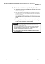
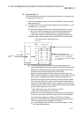
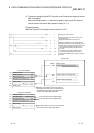
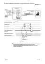
4) The device completing the INPUT instruction turns ON when the reading of receive
data is completed.
When the complete device + 1 (abnormal completion signal) turns ON, the error
code is stored in the control data completion status (S1 + 1).
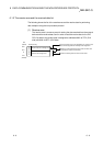
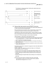
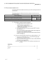
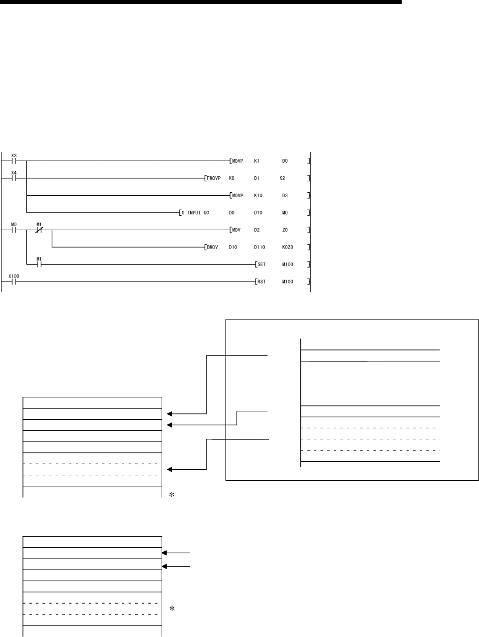
(Program example)
When the Q series C24 I/O signals are from X/Y00 to X/Y1F:
Designate the receive channel.
Clear the reception result and receive data count
storage device to 0.
Designate the allowable receive data count.
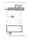
With normal completion, the receive data within the
allowable receive data count (user designated) is read
from the receive data storage area in the buffer memory.
Once the INPUT instruction is executed, the user
designated read completion signal (M0) turns ON
for 1 scan.
The reading of receive data and switching of the
ON/OFF status are performed by the PLC CPU.
•
•
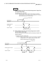
The abnormal completion flag is reset by an external
command.
Data received prior to an error occurrence will be
stored in the receive data storage device.
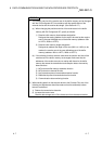
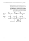
For normal completion
(1)
(0)
(n)
(10)
(1)
(other than 0)
(n)
(10)
Q series C24
D 0
D 1
D 2
D 3
D10
D m
Interface number
Reception result
Receive data count
Allowable receive data count
Receive data
Receive data
For abnormal completion
D 0
D 1
D 2
D 3
D10
D x
Interface number
Reception result
Receive data count
Allowable receive data count
Receive data
Receive data
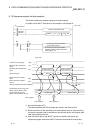
Buffer memory
Data reception result storage area
Receive data count storage area
Receive data storage area
Address
258
H
600
H
601
H
7FF
H
When the receive data count is larger than the
allowable receive data count, only the data up to
the allowable receive data count will be stored
and the excess data will be discarded.
From the buffer memory (address 258
H
)
From the buffer memory (address 600
H
)
to to
to
to to