


Page: 170
Service Manual for OF5800
Chapter 5 Disassembly
Before disassembling, disconnect the power cord, line cord and handset. Disassembly procedures for the
following items will be shown in this section.
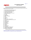
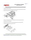
Document Hopper / Document Tray / Paper Hopper1.
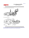
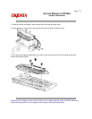
Main Control PCB, NCU PCB, Modular PCB2.
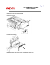
Front Cover and Control Panel PCB / LCD3.
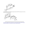
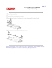
Scanner Assy and Scanner Frame4.
Inverter PC Board / Scanner Lamp5.
Scanner Assy A, B, C and Inter Lock Switch6.
TX Cover and Lock Lever7.
DS1 / DS28.
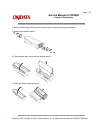
Press Roller9.
Separator Roller10.
Exit Roller / Feed Roller11.
Stamp12.
TX Motor13.
Contact Glass14.
Speaker15.
Connector PCB 1 / Connector PCB 216.
Printer I/F PCB/Printer Mechanical Controller PCB17.
Printer Unit18.
Image Transfer Unit19.
Printer Cover Unit20.
High Voltage Unit21.
Paper Sensor22.
Power Supply Unit23.
Heater Lamp24.
Fusing Unit25.
Thermistor26.
Paper Exit Sensor27.
Print Head Unit28.
Cassette PCB and PS/Cassette sensor29.
Pickup Roller W Assy and Solenoid30.
Feed Roller W and Press Roller W31.
Bottom Stay and Cassette Frame32.
Copyright 1997, Okidata, Division of OKI America, Inc. All rights reserved. See the OKIDATA Business
Partner Exchange (BPX) for any updates to this material. (http://bpx.okidata.com)