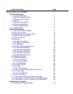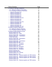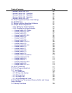
Table of Contents Page
5 Disassembly
5.0 Disassembly 170
5.1 Document Hopper / Document Tray / Paper Hopper 171
5.2 Main Control PCB , NCU PCB, Modular PCB 172
5.3 Front Cover and Control Panel PCB / LCD 173
5.4 Scanner Assy and Scanner Frame 174
5.5 Inverter PC Board / Scanner Lamp 175
5.6 Scanner Assy A, B, C and Inter Lock Switch 176
5.7 TX Cover and Lock Lever 177
5.8 DS1 / DS2 178
5.9 Press Roller 179
5.10 Separator Roller 180
5.11 Exit Roller / Feed Roller 181
5.12 Stamp 182
5.13 TX Motor 183
5.14 Contact Glass 184
5.15 Speaker 185
5.16 Connector PCB 1 / Connector PCB 2 186
5.17 Printer I/F PCB/Printer Mechanical Controller PCB 187
5.18 Printer Unit 188
5.19 Image Transfer Unit 189
5.20 Printer Cover Unit 190
5.21 High Voltage Unit (PWB-F) 191
5.22 Paper Sensor (PS) 192
5.23 Power Supply Unit (PWB-E) 193
5.24 Heater Lamp 194
5.25 Fusing Unit 195
5.26 Thermistor 196
5.27 Paper Exit Sensor 197
5.28 Print Head Unit 198
5.29 Cassette PCB and PS/Cassette sensor 199
5.30 Pickup Roller W assy and Solenoid 200
5.31 Feed Roller W and Press Roller W 201
5.32 Bottom Stay and Cassette Frame 202
6 Illustrated Parts List
Illustrated Parts List 203
....Illustrated Part List 1: Panel/Cover/Hopper 204
....Illustrated Part List 2A (1/3): Transmission 205
....Illustrated Part List 2B (2/3): Transmission 206
....Illustrated Part List 2C (3/3): Transmission 207
....Illustrated Part List 3: Scanner Frame 208
....Illustrated Part List 4: Bottom Chassis 209
....Illustrated Part List 5: Cassette 210
....Illustrated Part List 6: Power Supply 211


