


Page: 12
Service Manual for OF5800
Chapter 2 Machine Operations
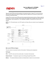
The power supply unit receives the input line voltage and converts it to output voltages of +5 VDC, +24
VDC,+12 VDC, and -12 VDC.
If an over current condition is sensed in the secondary circuit, power is interrupted.
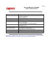
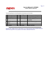
The power supply unit has three output connectors. The following table shows the connector outputs: CN1
to the Printer Mechanical Control PCB, CN2 to the Fuser Heater, and CN3 to the Main Control PCB.
CN1 Printer Mechanical Control PCB
Pin No. 1 2 3 4 5
Output +24V GND GND +5V H.L
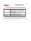
CN2 Fuser
Pin No. 1 2 3
Output N N.C L
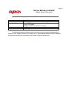
CN3 Main
Control
PCB
Pin No. 1 2 3 4 5 6 7 8
Output +24V +24V GND GND +12V -12V +5V +5V
Image and programmed data is backed-up in the event of a power failure.
Copyright 1997, Okidata, Division of OKI America, Inc. All rights reserved. See the OKIDATA Business
Partner Exchange (BPX) for any updates to this material. (http://bpx.okidata.com)