


79
Constructing Networks with Repeater Units Section 3-4
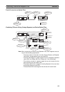
Units/Support Boards or Repeater Units) at both ends of each network
segment created by installing Repeaters must also be turned ON.
To construct a 62-node configuration in a wired network, all network nodes
must consist of one of the following models:
CS1W-CLK21-V1, CJ1W-CLK21-V1, 3G8F7-CLK21-V1
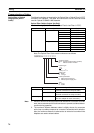
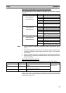
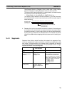
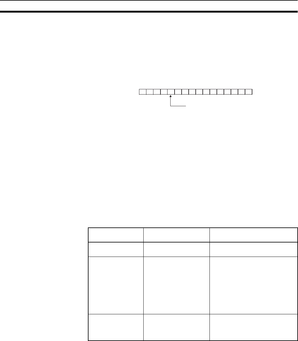
The following Wired Network 62 Node Enable Bit in the DM Parameter
Area software switch on each node must be turned ON to enable using 62
nodes maximum:
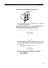
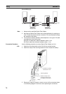
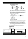
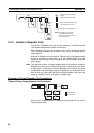
4. Repeater Units can be connected in a network in advance if new nodes are
to be added to the network after the system has been constructed. When
it becomes necessary to add a node, cabling can be accomplished easily
by simply wiring a T-Branch to the Repeater Unit. This method also allows
nodes to be added without stopping communications over the existing net-
work.
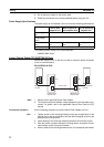
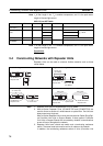
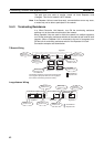
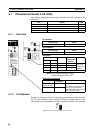
3-4-1 Segments
Repeater Units divide a wired Controller Link network into segments. Seg-
ments are comprised of nodes connected in a multi-drop configuration using
wire cables. The specifications of the network within a segment are identical
to the wired Controller Link network itself. The specifications within a single
segment are shown in the following table.
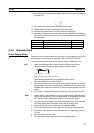
15 14 13 12 11 10 9 8 7 6 5 4 3 2 1 0
−−−− −−−−−−−−−−
−
Software switch
(D30000+100 ×
unit number)
Wired Network 62 Nodes Enable Bit
0: 32 nodes max.
1: 62 nodes max.
Item Specifications within
each segment
Remarks
Transmission line
type
Multi-drop ---
Baud rate and maxi-
mum transmission
distance
2 Mbps: 500 m
1 Mbps: 800 m
500 Kbps: 1 km
Because Repeater Units enable
up to 2 stages to be connected,
the maximum transmission dis-
tance of a network (i.e., the total
length of the longest path connect-
ing any two nodes) is as follows:
2 Mbps: 1.5 km
1 Mbps: 2.4 km
500 Kbps: 3 km
Maximum number of
nodes (Units)
32, including Controller
Link Units, Support
Boards, and Repeater
Units
Repeater Units do not use a node
address.