67
Wiring Section 3-3
3. Do not connect the shield cable of the communications cable to a ground
that is also being used for power-system devices, such as inverters.
4. Ground the shield line of the communications cable at one end of the net-
work. Do not ground the shield at both ends.
5. Do not run wiring outdoors. If outdoor wiring is necessary, take protective
measures against lightning, such as underground wiring or wiring inside
pipes.
6. The minimum length of the communications cable between nodes is 1 m.
Prepare the communications cables at a length of 1 m or more.
7. Use the multidrop method for connecting nodes. Normal communications
will not be possible with T branches.
8. Turn ON the terminating resistance switch at the nodes at both ends of the
network to connect terminating resistance. Turn OFF the terminating resis-
tance switch at all other nodes.
9. A label has been placed over the upper surface of the Controller Link Unit
to prevent scraps of wire from entering the Unit. Conduct wiring and instal-
lation with this label in place. If wire scraps get into the Unit, it will malfunc-
tion (C200HW-CLK21, CS1W-CLK21-V1, CJ1W-CLK21-V1, and CQM1H-
CLK21 only).
10. Remove the label after wiring to avoid overheating. Overheating will cause
the Unit to malfunction (C200HW-CLK21, CS1W-CLK21-V1, CJ1W-
CLK21-V1, and CQM1H-CLK21 only).
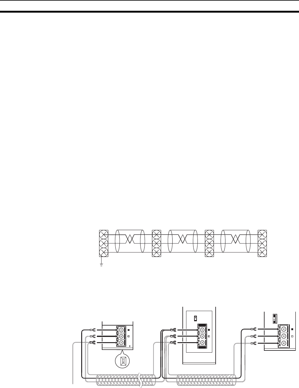
Connecting the Shield Line
Connect both ends of the shield line to the terminal blocks and earth the ter-
minal block at the one end of the network.
Terminal Block Connections
Not Unit a Relay Terminal Block
Note Use the recommended crimp terminals when connecting the cable’s signal
lines or shield line to the terminal blocks. Short circuits can damage the Units.
BD
BD
SHLD
H
L
g
#
TER SW
↓
ON
BD H
BD L
SHLD
TER
SW
↓
ON
↓
ON
BD H
BD L
SHLD
TER SW
BD H
BD L
SHLD
C200HW-CLK21
(End node)
Terminating
resistance
(ON)
Ground
Terminating
resistance
(OFF)
CVM1-CLK21
Terminating
resistance
(ON)
CS1W-CLK21-V1
CJ1W-CLK21-V1
(End node)


