


215
Commands and Responses for C200HX/HG/HE and CQM1H-series PLCs Section 6-6
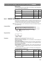
Memory Areas
The following areas can be read. (Refer to 6-6-2 Memory Area Designations
for PLC word/bit address designations):
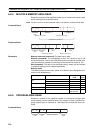
6-6-4 MEMORY AREA WRITE
Writes data to the specified number of consecutive words starting from the
specified word. All words must be in the same memory area. (Here, all mem-
ory areas with the same memory area code are considered as one area).
Note When data is written to the Timer/Counter PV area, the Completion Flags will
be turned OFF (0).
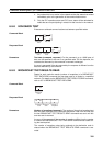
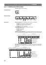
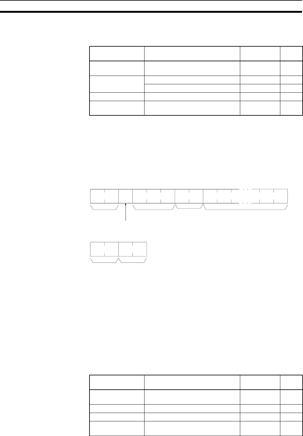
Command Block
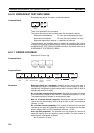
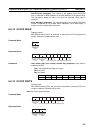
Response Block
Parameters Memory area code (command): The data area to write.
Beginning address (command): The first word/value to write. Specify 00
(Hex) for the 3rd byte.
No. of items (command): The number of items to be written. Specify 0000 to
03E5 (Hex) (0 to 997 decimal). The command can be completed normally
even if zero items are specified.
Data (command): The data to be written. PVs for timers and counters are
written as BCD. The required number of bytes in total is calculated as follows:
2 bytes
× No. of items
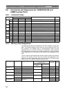
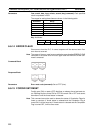
The following data can be written. (Refer to 6-6-2 Memory Area Designations-
for the word/bit address designations):
Memory area Data Memory area
code
No. of
bytes
IR, SR, LR, HR, or
AR
Word contents 80 2
Timer/Counter Completion Flag status 01 1
PV 81 2
DM Word contents 82 2
Expansion DM Word contents 90 to 97, 98,
and A8 to AF
2
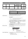
Command
code
01 02
Beginning address
Memory area code
StatusNo. of items
00
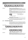
Command
code
01
02
Response
code
Memory area Data Memory area
code
No. of
bytes
IR, SR, LR, HR, or
AR
Word contents 80 2
Timer/Counter PV 81 2
DM Word contents 82 2
Expansion DM Word contents 90 to 97, 98,
and A8 to AF
2