


300
Status Area and Troubleshooting Section 9-2
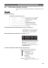
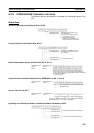
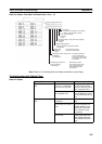
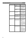
Polling Node Address, Startup Node Address: SR 238, SR 242
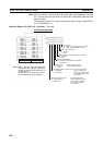
Data Link Status: SR 239
to SR 241, SR 243 to
SR 245
When the data link status stored in the start word for the manual setting data
link table or automatic setting data link parameters is not set or is set to 0, the
data link status of only node addresses 1 to 6 will be displayed in the following
area.
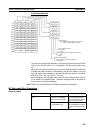
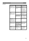
Operating Level Status: SR 252
Note Data link status is valid only when the local node is participating in the data
link. Confirm that the local node’s data links are active in the operating level
status in SR 252 before referencing the data link status.
Operating level 0
SR 238
Operating level 1
SR 242
Polling node address Startup node address
Each node address is displayed in 2-digit BCD.
Operating
level 0
SR 239
SR 240
SR 241
Operating
level 1
SR 243
SR 244
SR 245
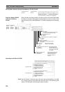
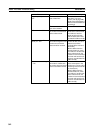
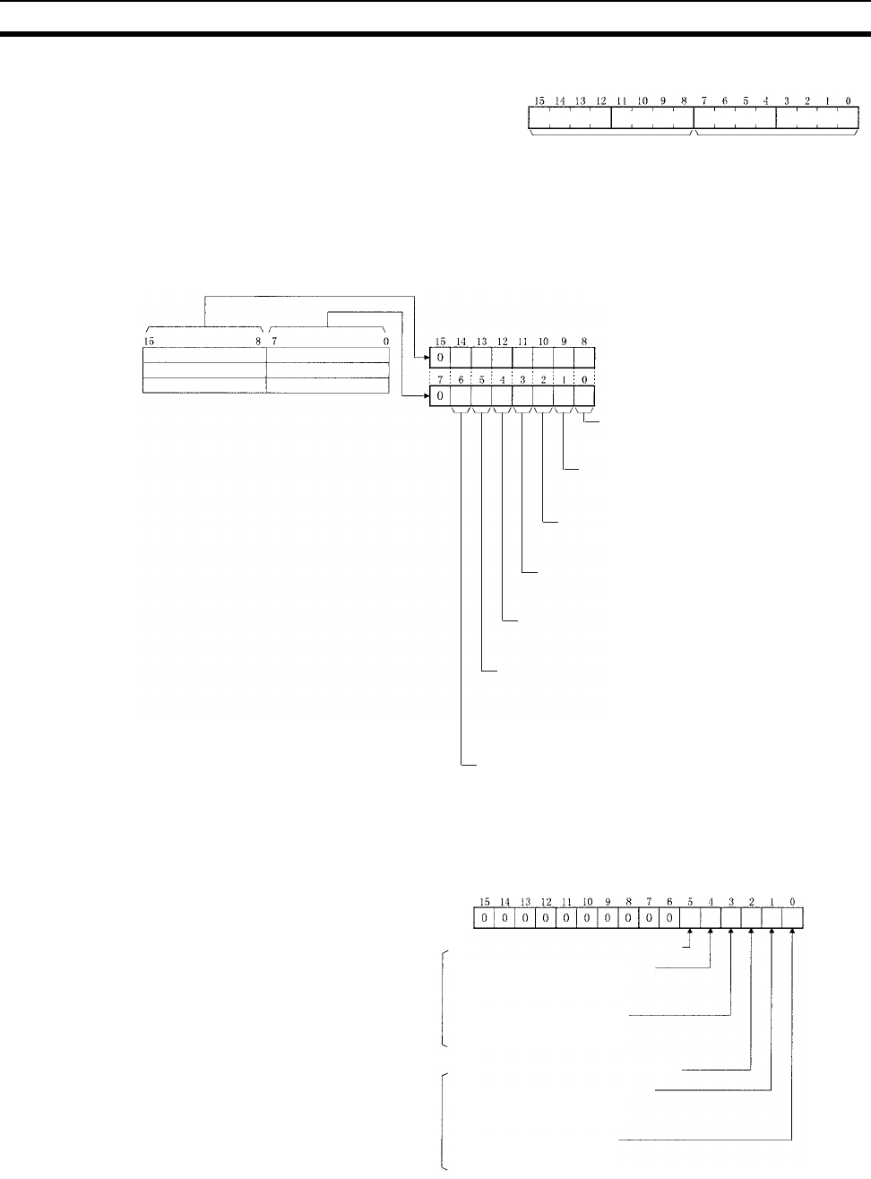
PLC status
0: Inactive (user program not running)
1: Active (user program running)
Communications error (data link reception)
0: Normal
1: Error
PLC's CPU Unit error
0: Normal
1: Error
Data link participation
0: Not in data link or data link inactive
1: In data link
Offset error
0: Normal
1: Error
Error: Offset exceeds
number of send words.
Insufficient (short) receive area
0: Sufficient
1: Insufficient
Insufficient: Receive
area is smaller than
send area. Excess data
is truncated; other data
is received.
Remaining receive area
0: Not remaining
1: Remaining
Remaining: Receive area
is larger than send area.
Data is received and
remaining words are
cleared.
Node 2
Node 4
Node 6
Node 1
Node 3
Node 5
Operating level 1
Operating level 0
SEND/RECV Enable Flag
0: Disabled (operating)
1: Enabled (not operating)
SEND/RECV Error Flag
0: Normal completion
1: Error
SEND/RECV Enable Flag
0: Disabled (operating)
1: Enabled (not operating)
1: Local node data link participating
SEND/RECV Error Flag
0: Normal completion
1: Error
1: Local node data link participating