


53
Component Names and Functions Section 3-1
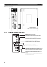
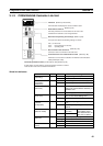
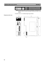
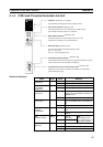
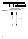
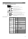
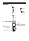
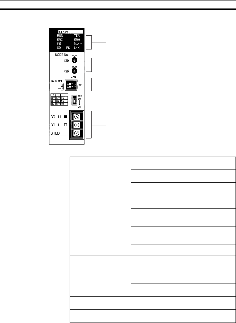
3-1-5 CQM1H-series Controller Link Unit
Wired Unit Indicators
Indicators
LED indicators that display the Unit and network status.
Node address switches
Two rotary switches. The node address of the Unit on the
Controller Link Network is set in 2-digit decimal.
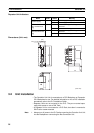
Baud rate switch
Terminal block for the communications cable
Terminals to connect to the Controller Link Network communications
cable (twisted-pair cable).
Terminating resistance switch
A slide switch. Use this switch to set the terminating resistance to ON for
the nodes at both ends of the Controller Link Network.
bit/s
k
(Refer to p. 53 and 276)
(Refer to p. 101)
(Refer to p. 101)
(Refer to p. 102)
(Refer to p. 66)
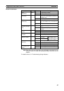
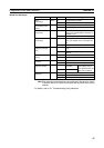
Name Color Status Meaning
RUN
(operating)
Green Lit Unit operating normally.
Not lit Unit error.
TER
(terminating
resistance)
Yellow Lit Terminating resistance switch ON.
Not lit Terminating resistance switch OFF.
ERC (communica-
tions error)
Red Lit Communications error, node address
setting error (same address set twice), or
hardware error.
Not lit Normal operation
ERH
(PLC error)
Red Lit PLC error, PLC interface error, or
EEPROM error
Not lit No error.
INS
(network
participation)
Yellow Lit Unit is participating (inserted) in the net-
work.
Not lit Unit is not participating (inserted) in the
network.
M/A
(data link mode)
Yellow Lit Manual
(see note)
Note:
M/A is always not lit
when data links are not
active in the network.
Not lit Automatic
LNK
(data link)
Yellow Lit Participating in data links.
Flashing Error in data link tables.
Not lit Not in a data link or data link inactive.
SD
(send)
Yellow Lit Data transmission.
Not lit No data transmission.
RD
(receive)
Yellow Lit Data reception.
Not lit No data reception.