


58
Unit Installation Section 3-2
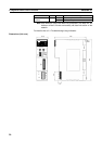
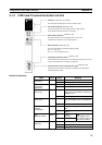
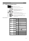
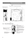
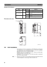
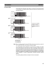
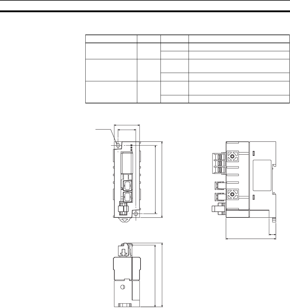
Repeater Unit Indicators
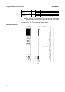
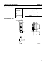
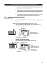
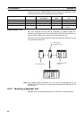
Dimensions (Unit: mm)
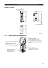
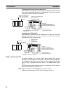
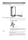
3-2 Unit Installation
• The Controller Link Unit is mounted onto a CPU Backplane or Expansion
CPU Backplane for use. For detailed information on into a PLC installation
procedures, refer to the PLC Installation Guide.
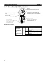
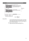
• Repeater Units are not mounted to the PLC. They are mounted sepa-
rately with screws or onto a DIN Track.
• A Repeater Unit is not mounted to a PLC Rack, but rather is mounted to
DIN Track or screw-mounted.
Note 1. Always turn off power to the PLC before mounting the Controller Link Unit
into the Backplane or connecting the Bus Connection Unit.
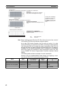
Name Color Status Meaning
PWR
(Power supply)
Green Lit Power supply is ON.
Not lit Power supply is OFF.
T/R1
(SL1 communicat-
ing)
Yellow Lit Transmission signal is being sent or
received.
Not lit No transmission signal.
TR2
(SL2 2 communicat-
ing)
Yellow Lit Transmission signal is being sent or
received.
Not lit No transmission signal.
75.6
73.3
8
59
Two, 4.5 dia.
(30)
90
21
81
(Unit: mm)