


46
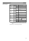
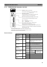
Component Names and Functions Section 3-1
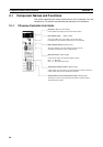
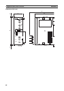
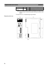
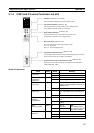
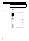
Dimensions (Unit: mm)
3-1-2 CJ-series Controller Link Units
101
35
130
CLK21-V1
UNIT
No.
RUN
CLK21-V1
ERC INS
ERH M/A LNK RD
NODE
No.
x10
1
x10
0
0
1
2
3
4
5
6
7
8
9
A
B
C
D
E
F
0
TER
SD
1
2
3
4
5
6
7
8
9
0
1
2
3
4
5
6
7
8
9
BAUD
RATE
1
2
ON
SW1
ON
TER SW
BD H
BD L
SHLD
ON
1
2
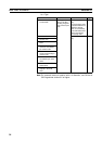
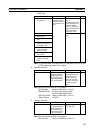
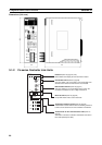
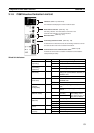
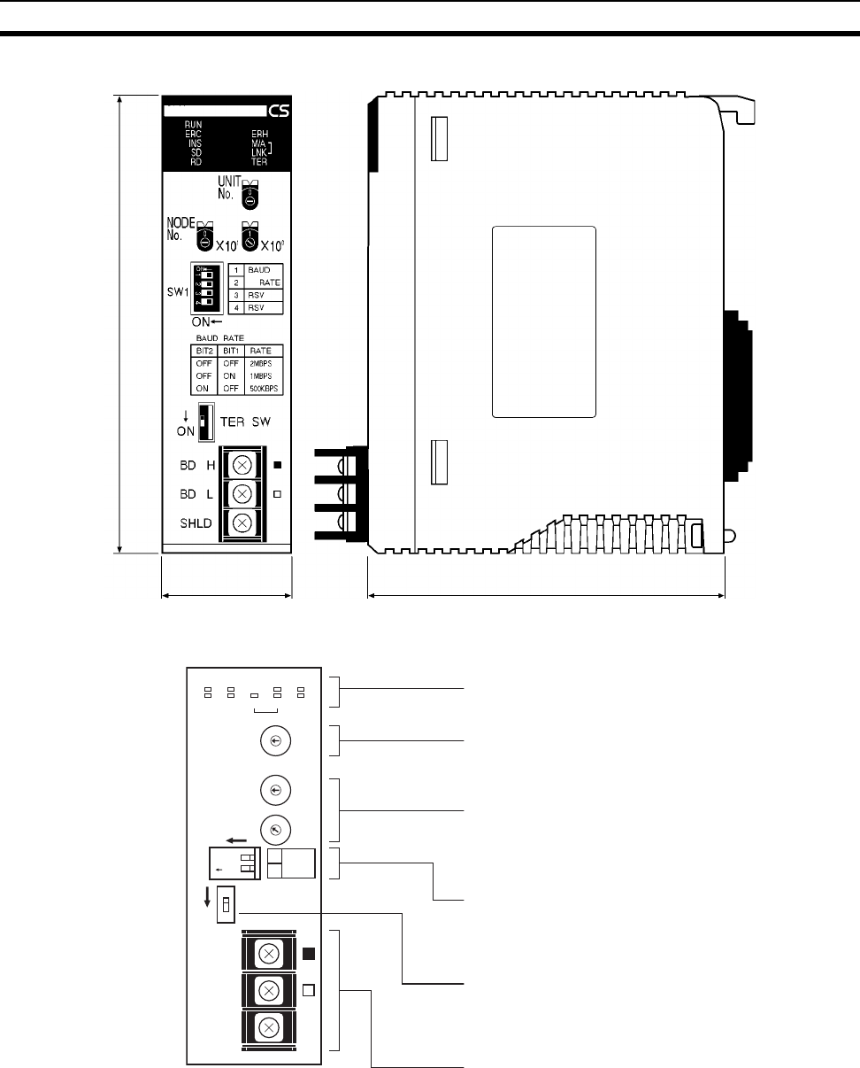
Indicators (Refer to pages 45, 276)
LED indicators that display the Unit and network status.
Unit Number Switch (Refer to page 86)
One rotary switch. The unit number is set in single-digit hexa-
decimal for the network to which the PLC is connected.
Node address switches (Refer to page 87)
Two rotary switches. The node address of the Unit on the
Controller Link Network is set in 2-digit hexadecimal.
Baud rate switch (Refer to page 88)
A 2-pin DIP switch used to set the baud rate.
Terminating resistance switch (Refer to page 89)
A slide switch. Use this switch to set the terminating resistance
to ON for nodes at both ends of the Controller Link Network.
Terminal block for the communications cable (Refer to
page 64)
Terminals to connect the Controller Link Network communica-
tions cable (twisted-pair cable).