


122
Setting Data Links Section 5-2
(Data link start word – 1) + Total number of send/receive
words in area
≤247 (IR Area)
63 (LR Area)
5999 (DM Area)
6143 (EM Area)
c) Refer to the Controller Link Support Boards Operation Manual
(W307) for information on the Controller Link Support Board.
d) If CX-Net detects an error during the data link table check, trou-
bleshoot the error referring to
9-4 Troubleshooting Error Mes-
sages in CX-Net Data Link Table Check
.
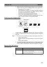
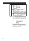
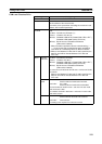
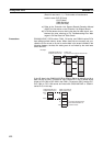
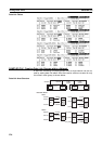
Precautions C200HX/HG/HE, CS/CJ-series, CVM1, CV-series, and CQM1H-series PLCs
have different-sized memory areas. When data links are manually set, pro-
vided the PLCs are set so as not to receive data in the areas indicated in the
following diagram, the data link setting area is not limited by the small area
size of the PLC.
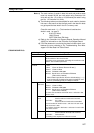
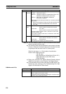
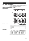
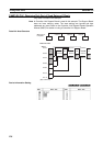
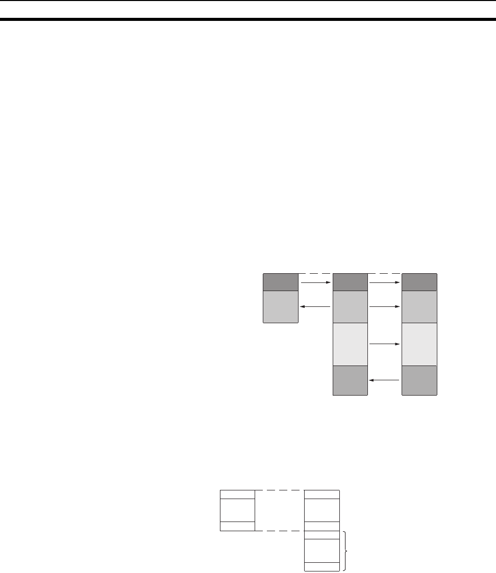
If the LR Area in the C200HX/HG/HE or CQM1H Series is manually set for a
data link with a CVM1, CV-series or CS/CJ-series PLC, the LR words will be
linked to CIO 1000 to CIO 1063 in the CVM1, CV-series or CS/CJ-series PLC.
CIO 1064 to CIO 1199 cannot be linked with C200HX/HG/HE or CQM1H-
series PLCs in this way.
to
0
235
100
335
336
200
435
436
CVM1 and
CV-series PLCs
C200HX/HG/HE and
CQM1H-series PLCs
Example:
CS/CJ-series PLCs
Cannot be directly linked
with C200HX/HG/HE or
CQM1H words.
LR00
LR63
to
1000
1063
to
1064
1199
to
CVM1, CV-series or
CS/CJ-series PLCs
C200HX/HG/HE and
CQM1H-series PLCs