


34
Data Links Procedures Section 2-1
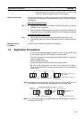
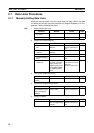
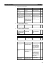
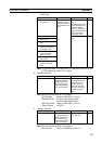
8. Start the data links.
Note a) Data link Start/Stop Bit (N= unit number):
CS/CJ Series: Word 0 of DM30000 + 100
× N
C200HX/HG/HE: AR 0700 (operating level #0),
AR 0704 (operating level #1)
CVM1/CV Series: Word 0 of DM 2000 + 100
× N
CQM1H Series: AR 0700
b) The data links will not start if there is an error in the data link
tables in the startup node.
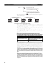
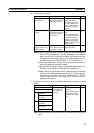
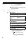
9. Stop the data links.
Note Data link Start/Stop Bit (N= unit number):
CS/CJ Series: Word 0 of DM30000 + 100
× N
C200HX/HG/HE: AR 0700 (operating level #0),
AR 0704 (operating level #1)
CVM1/CV Series: Word 0 of DM 2000 + 100
× N
CQM1H Series: AR 0700
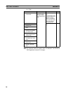
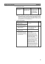
2-1-2 Automatically Setting Data Links
Data link tables can be automatically created by setting the data link mode to
automatic data link table creation. Use the following procedure.
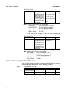
1,2,3... 1. Install and wire the Units.
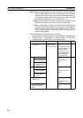
Contents Method Nodes Page
Start the data links. Switch the Data link
Start/Stop Bit (listed
below) from OFF to
ON using either the
Programming Device,
the user program, the
Controller Link Sup-
port Software or CX-
Programmer.
Data link startup node
(The Start Bit can be
turned ON in more
then one node to
make sure the data
links start even when
the startup node is
down.)
153
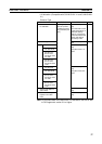
Contents Method Nodes Page
Stop the data links. Switch the Data link
Start/Stop Bit (listed
below) from OFF to
ON using either the
Programming Device,
the user program, the
Controller Link Sup-
port Software or CX-
Programmer.
Any node that is active
in the data link
153
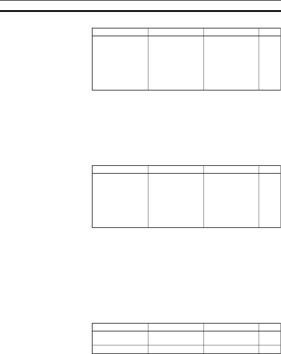
Contents Method Nodes Page
a. Mount the Units to
the PLCs.
--- All nodes 59
b. Wire the Network.
--- All nodes 66