


139
Setting Data Links Section 5-2
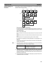
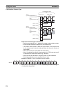
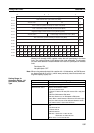
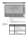
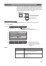
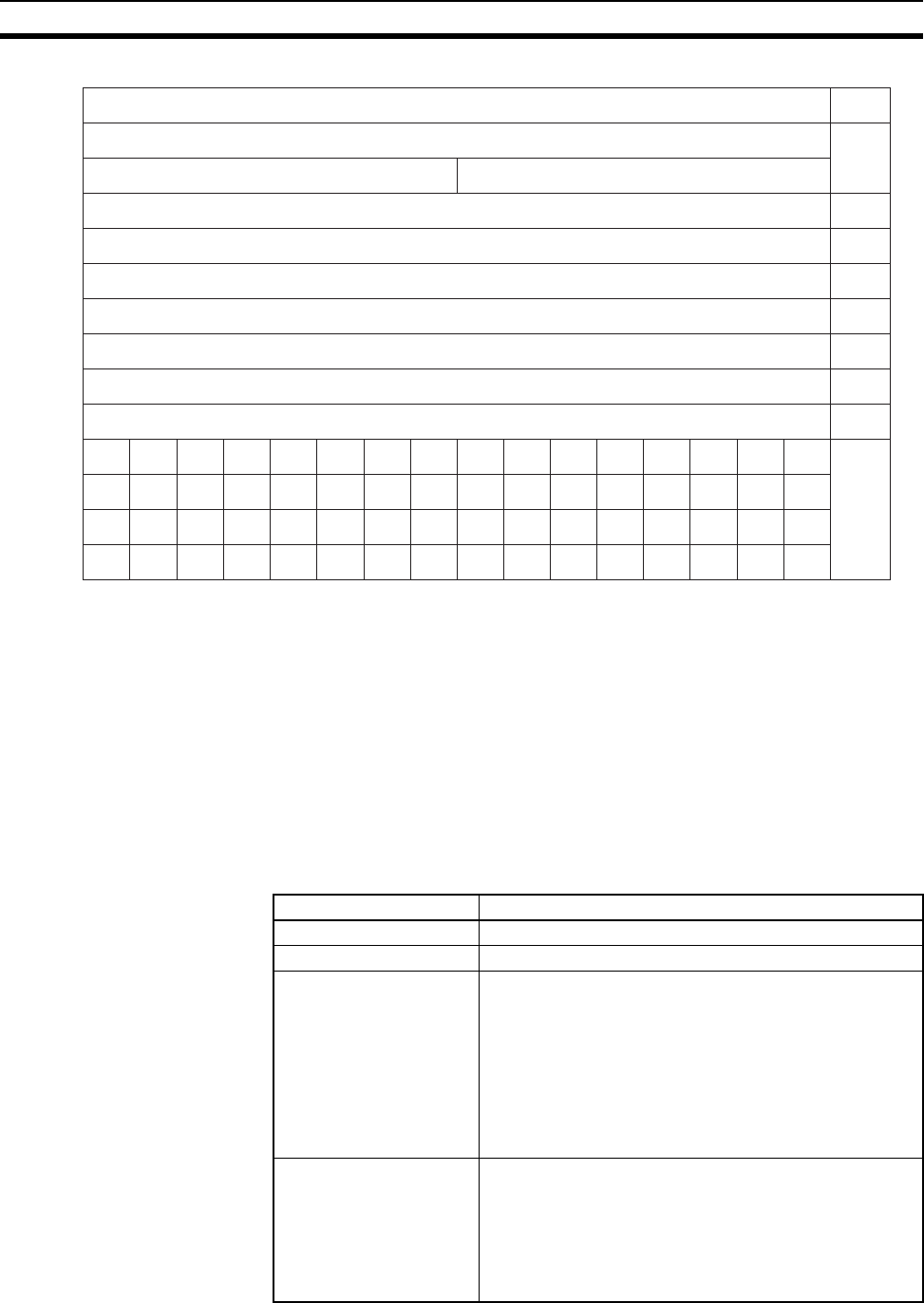
Words N+22 through N+25 register nodes that will participate in the data
links. The numbers in the table are the node addresses. The bit status given
for each node address indicates whether the node is to participate in the data
links.
Participate: ON
Not participate: OFF
Note 1. Leave the reserved words set to 0 (N+18 to N+20).
2. When using automatic data link creation with 1:N allocations, set DM Pa-
rameter Area words N+2 to N+11 (which were previously used for automat-
ic setting with equality layout) to 0.
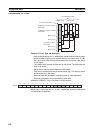
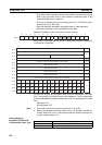
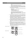
Setting Ranges for
Automatic Creation with
1:N allocations, 1 to 1
Type
15 8 7 0
N+12
---
N+13
N+14
(1)
N+15
(2)
N+16
(3)
N+17
(4)
N+18
---
N+19
---
N+20
---
N+21
---
N+22 16 15 14 13 12 11 10 9 8 7 6 5 4 3 2
1
N+23323130292827262524232221201918
17
N+24484746454443424140393837363534
33
N+25
--- ---
62 61 60 59 58 57 56 55 54 53 52 51 50 49
(5)
1:N allocation type setting (
Set value 0002 = 1 to 1 type
)
Rightmost 4 digits of start word (BCD)
Area
Number of common send words for master node (BCD)
Number of individual send words for master node (BCD)
Number of send words for slave nodes (BCD)
0000 (Reserved)
0000 (Reserved)
0000 (Reserved)
First word to store data link status (bit-access area) (BCD)
Leftmost digit of area start word (BCD)
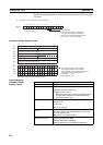
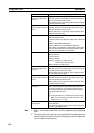
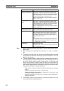
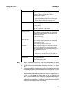
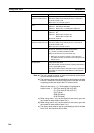
Item Setting range
Data link mode Specify automatic data link creation with 1:N allocations.
1:N allocation Specify 1 to 1 type.
Area start word Set the word address in BCD.
IR or CIO Area: 0 to 6143
LR Area: LR 000 to LR 199 (1000 to 1199) (See note.)
DM Area: D00000 to D32767
EM Area: Banks 0 to 12 E00000 to E32767
Note: When a word between LR 000 and LR 199 is spec-
ified, the data link area will be allocated between words
1000 and 1199 in the IR or CIO Area.
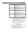
Area type Set the area type of area 1 as a hexadecimal number.
IR Area: 80 Hex
LR Area: 86 Hex
DM Area: 82 Hex
EM Area Banks 0 to 7: 90 to 97 Hex
Banks 8 to 12: A8 to AC Hex