


225
Response Codes Section 6-7
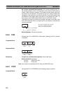
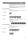
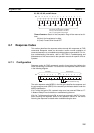
IR, SR, LR, HR, and AR Areas:
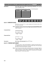
Timers/Counters: Status of the Completion Flag will be returned as fol-
lows:
00 (Hex): No forced status in effect
01 (Hex): Forced ON or forced OFF
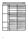
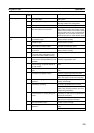
6-7 Response Codes
This section describes the response codes returned with responses to FINS
commands. Response codes can be used to confirm normal completion of
command execution or to troubleshoot problems when commands fail. For fur-
ther troubleshooting information, refer to SECTION 9 Troubleshooting and
Maintenance of this manual and to the operation manuals for specific Units or
Systems.
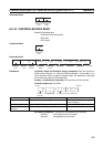
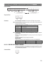
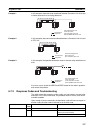
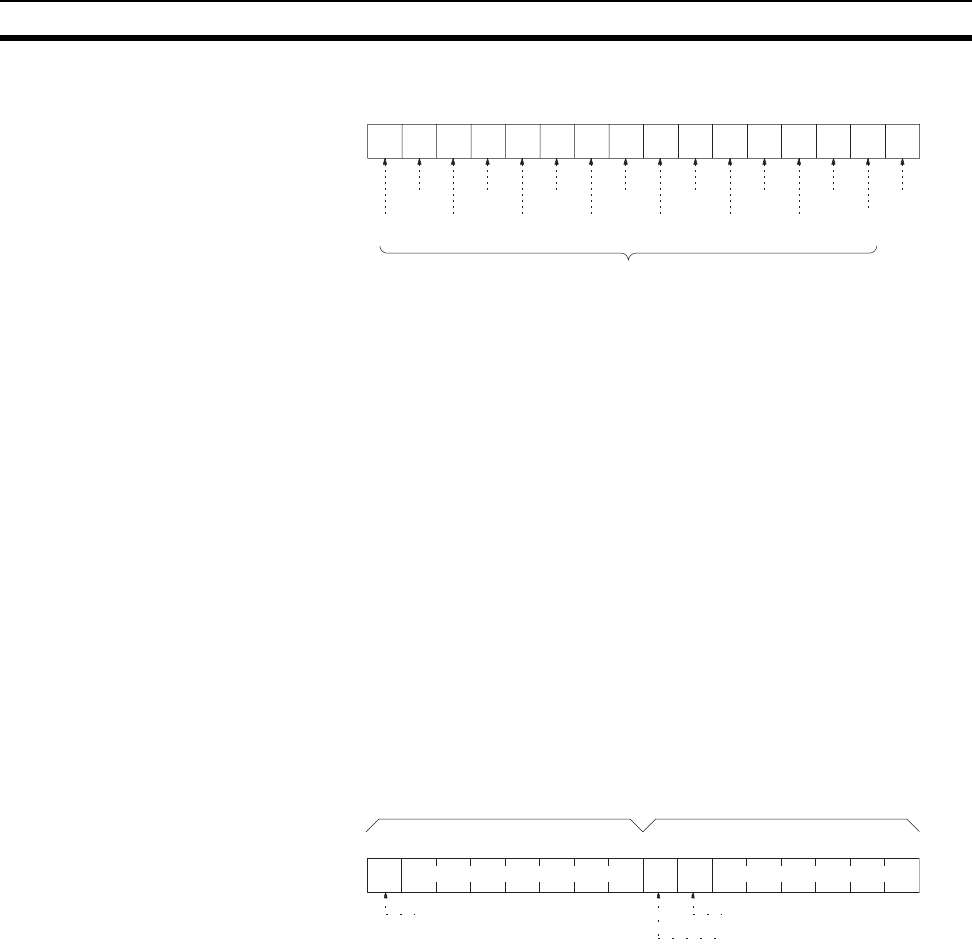
6-7-1 Configuration
Response codes for FINS commands consist of two bytes that indicate the
result of executing a command. The structure of the response codes is shown
in the following diagram.
The main response code (MRES) in the first byte classifies the response and
the sub-response code (SRES) in the second byte indicates details under the
MRES classification.
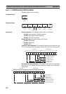
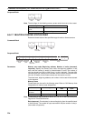
If bit 7 of the first byte is ON, a network relay error has occurred. Refer to 6-7-
2 Network Relay Errors for details on troubleshooting the error.
If bit 6 or 7 of the second byte is ON, an error has occurred in the PLC or com-
puter returning the response. Refer to the operation manual for the device
returning the response for details when troubleshooting the error.
Bit 0
15 14 13 12 11 10 9
876543210
Bit
Bit 1
Bit 2Bit 4Bit 6Bit 8Bit 10Bit 12Bit 14
Bit 3Bit 5
Bit 9 Bit 7Bit 11Bit 13Bit 15
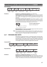
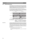
The status for each bit is as follows:
OFF (0): No forced status in effect
ON (1): Forced ON or forced OFF
7654321076543210
Bit
1: PLC Non-fatal Error Flag
1: PLC Fatal Error Fla
g
1: Relay Error Flag
First byte Second byte
Main response code (MRES) Sub-response code (SRES)