


61
Unit Installation Section 3-2
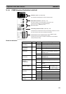
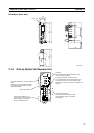
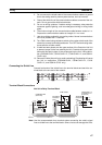
CS-series PLCs
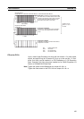
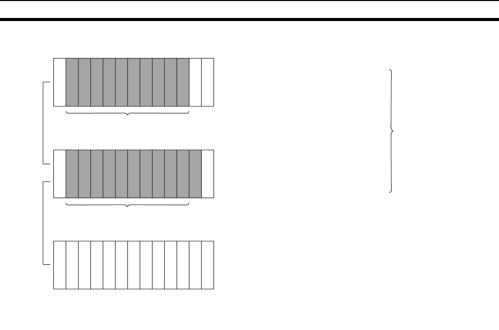
Up to a total of eight Controller Link Units with unit version 1.2 or later (wired,
optical, and optical ring) for CS-series PLCs (or up to four pre-Ver. 1.2 Con-
troller Link Units) can be installed in a CPU Backplane or a CS Expansion
Rack. Controller Link Units cannot be installed on an C200H Expansion I/O
Rack or a SYSMAC BUS Slave Rack.
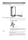
Note Tighten the screws on the Backplane to a torque of 0.9 N • m.
Tighten the fixed screws on the CPU Unit to a torque of 0.4 N • m.
CPU Backplane
Expansion
Backplane
2/3/5/8/10 slots
3/5/8/10 slots
CPU
Unit
Of these
slots,
installation is
possible in up
to 8 slots (unit
Ver. 1.2 or
later).
Installation in
up to 4 slots
is possible for
pre-Ver. 1.2
Units.
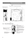
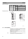
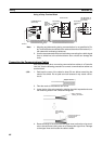
CPU Rack
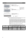
(CV500/CV1000/CV2000/CVM1)
The Unit can be mounted to the 3/5/10 slots
shown in the diagram on the right. (It cannot
be mounted to the leftmost slot even if an
Expansion CPU Rack is not used.)
Install in four of
these 14, 16, or
21 slots.
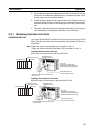
CPU Backplane
CV500-BC101, CVM1-BC103/CV500-BC051, CVM1-BC053/CV500-BC031
I
O
C
C
P
U
P
S
3/5/10 slots
Expansion CPU Rack
CV500/BI111
I
O
I
F
P
S
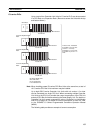
Expansion CPU Rack
Any of the 11 slots shown in the illustration
can be used. The leftmost slot cannot be
used.
I
O
I
F
P
S
Expansion I/O Rack
Controller Link Units cannot be mounted to
Expansion I/O Racks.
11 slots
PS: Power Supply Unit
CPU: CPU Unit
IOC: I/O Control Unit
IOIF: I/O Interface Unit