


40
Message Service Procedure Section 2-2
C200HX/HG/HE: AR 0700 (operating level #0),
AR 0704 (operating level #1)
CVM1/CV Series: Word 0 of DM 2000 + 100
× N
CQM1H Series: AR 0700
Note The data links will not start if there is an error in the data link tables
in the startup node. Data links can be started and stopped using the
Controller Link Support Software.
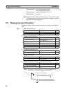
2-2 Message Service Procedure
The following steps outline the basic procedure for using the message ser-
vice.
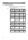
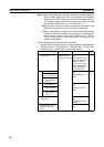
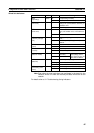
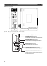
1,2,3... 1. Install and wire the Units.
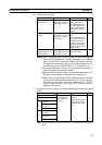
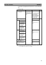
2. Prepare for communications.
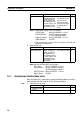
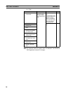
3. Turn ON the power to the PLC.
4. Create the I/O tables.
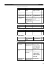
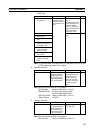
5. Register routing tables if using inter-network connections.
Contents Remarks Page
a. Mount the Units to the PLCs.
--- 59
b. Wire the Network.
--- 66
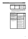
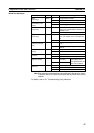
Contents Remarks Page
a. Set the unit number.
CS/CJ-series, CVM1, and CV-
series PLCs only
98
b. Set the node address.
--- 94, 98
c. Set the baud rate.
--- 95, 99
d. Set the operating level.
C200HX/HG/HE PLCs only 95
e. Set the terminal resistance.
--- 96, 99
Contents Remarks Page
Turn ON the power to the PLC. --- ---
Contents Remarks Page
Create the I/O tables. CS/CJ-series, CVM1, and CV-
series PLCs only
---
Contents Remarks Page
a. Set the local network table
--- 237
b. Set the relay network table
---
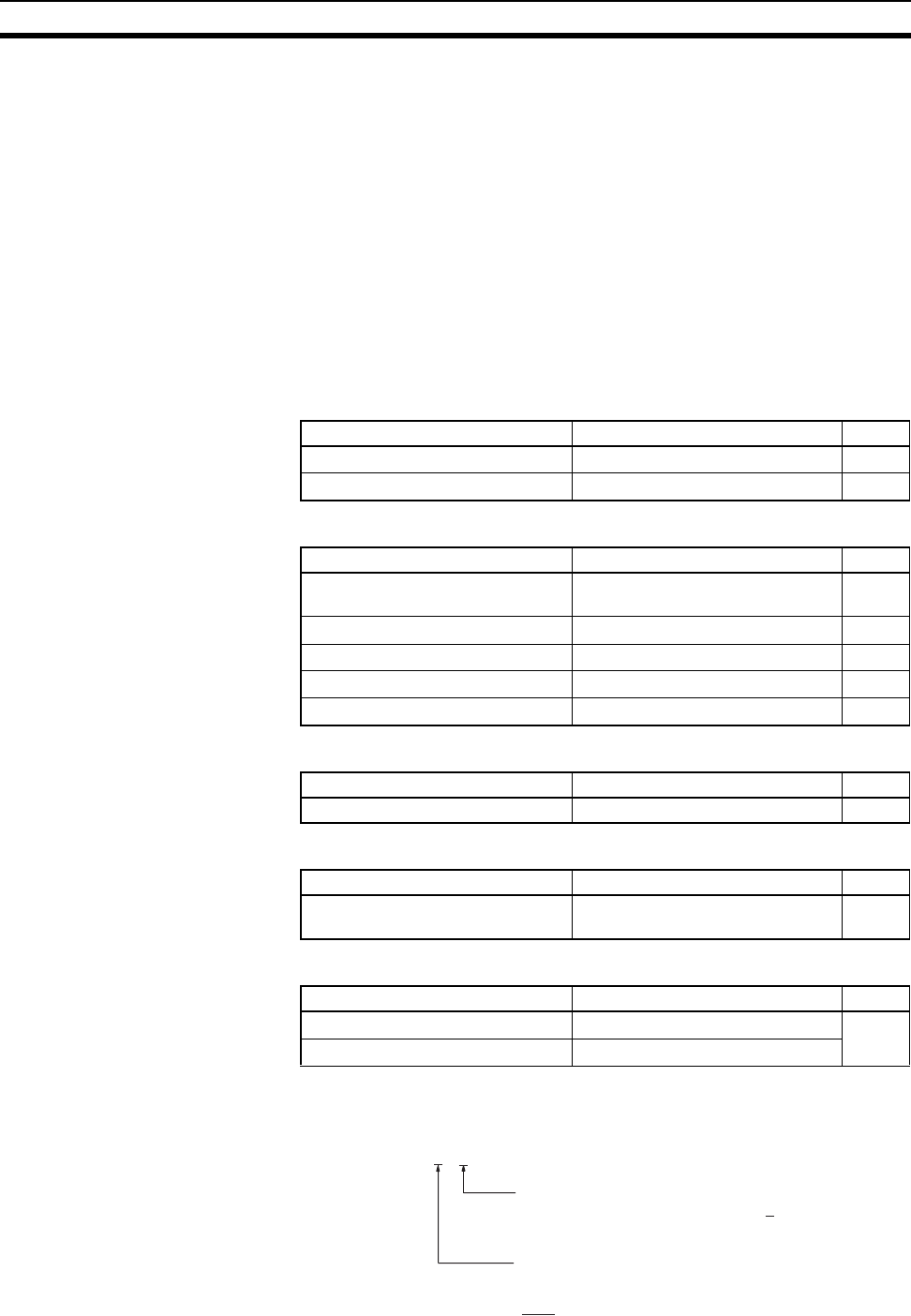
Lot No.: @ @ 4 6 .....Manufactured in April 1996
Indicates the last digit of the manufacturing
year. In this example, the year is 1996.
Indicates the month of manufacture. October,
November, and December are indicated by x, y,
and z respectively. In this example, the month is
April.
Note
Routing tables are required if any of the CVM1 and CV-series CPU Units
in the Network has been manufactured on or before April 1996.