


240
Setting Routing Tables Section 7-4
2. The network address is the address of the network connected to the Unit
(between 1 and 127). The address is set when the local network table is
created.
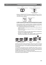
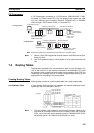
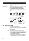
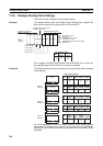
Relay Network Table A relay network table provides the node and network addresses correspond-
ing to the initial relay point (first point the data must go to) en route to a target
network (end network) not directly connected to the local PLC.
The table traces the route from the relay point to the end network.
The example below shows the routing tables for the route from local node
PLC1 (network address 1, node address 1) to PLC4 (network address 3, node
address 2).
7-4 Setting Routing Tables
This section describes routing table settings.
Routing tables are set through the CX-Net (in CX-Programmer), SYSMAC
LINK, or Controller Link Support Software. This section describes setting pro-
cedures and setting details.
See the operating manual of the Programming Device you are using for the
specific setting procedure.
Note 1. Routing tables cannot be set through Programming Consoles.
2. Networks cannot be crossed by a Programming Device without setting
routing tables. Routing tables can therefore be set only for nodes connect-
ed to the Programming Device and other nodes in the same network. Dis-
connect and reconnect the Programming Device to each network when
setting routing tables in multiple networks.
3. Make sure that the routing tables are properly set at all nodes on the net-
work. If a message is sent to a node without correct routing tables, trans-
mission will not work properly and a response may not be returned.
Local
network
address
Local node PLC1
Node
address
1
Relay node PLC2
Relay node
PLC3
Node address 2
Unit number 0
Node address 1
Unit number 1
Destination
Destination
node PLC4
End network
PLC1 relay network table PLC2 relay network table PLC3 local network table
End
network
Relay
network
Unit number
Data first goes to
node address 3 at
network address 1 to
reach network
address 3.
Data then goes to
node address 2 at
network address 2
to reach network
address 3.
We know from the
local network table
that the data goes
through local unit
number 1 to reach
network address 3.
Data goes to
node address 2
at network
address 3, i.e.,
the local
network.
Network address 1
Network
address 2
3
2
1
3
3
1
1
20
3
3
2
2
Node
address
2
Node
address
3
Node
address 1
Network
address 3
End
network
Relay
network
Relay
node
Relay
node
Node address 2