


100
CQM1H-series Controller Link Units Section 4-5
Note 1. Always turn OFF the PLC’s power before setting the terminating resistance
switch.
2. Turn ON the switch to connect terminating resistance at the nodes at both
ends of the Network and turn OFF the switch at all other nodes. Normal
communication cannot be performed in the Network unless all the nodes
are set properly.
3. The TER indicator will light when the terminating resistance switch is set
to ON.
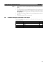
4-5 CQM1H-series Controller Link Units
The following settings are required for a Controller Link Unit when used with a
CQM1H-series PLC.
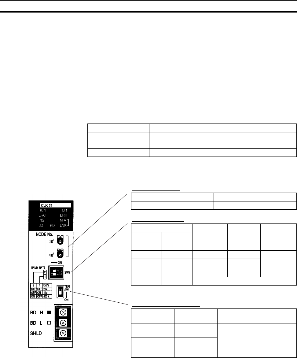
4-5-1 Overview
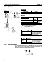
Node Addresses
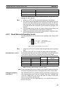
Setting Baud Rate
Note The factory default setting is in bold.
Terminating Resistance
Item Switch Page
Node address Node address switch 101
Baud rate Baud rate switch, pins 1 and 2 101
Terminating resistance Terminating resistance switch 102
Setting range Nodes
01 to 32 (default is 01) All nodes in the Network
Switch Baud rate Maximum
transmis-
sion dis-
tance
Nodes
Pin 1 Pin 2
OFF OFF 2 Mbps 500 m Set same
rate for all
nodes in Net-
work.
ON OFF 1 Mbps 800 m
OFF ON 500 Kbps 1 km
ON ON Do not set.
Switch Terminating
resistance
Nodes
OFF
(default)
Not connected All the nodes
Turn ON the terminating resis-
tance at the nodes at both
ends of the Network and turn it
OFF at all other nodes.
ON Connected