


5-1SectionConnecting to the Host’s RS-232C Port
95
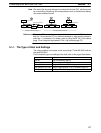
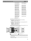
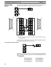
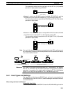
The relay terminal board is not included in the figure below. Insert a relay termi-
nal board so as to achieve the wiring configuration indicated below.
:
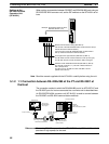
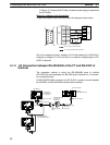
RS-422A
NT31/NT31C
Host
NT-AL001
:
1
14
13 25
1
14
13 25
NT31/NT31C side
Shielding wire
(25-pin type)
Abbreviation
FG
−
SD
RD
RS
CS
−
SG
−
TRM
RDB (+)
RDB (+)
−
−
−
SDA (−)
RDA (−)
−
−
RSB (+)
RSA (−)
−
Pin number
Connector
hood
1
2
3
4
5
6
7
8
9
10
11
12
13
14
15
16
−
23
24
25
RS-232C/
422A/485
connector
RS-232C/
422A/485
connector
Abbreviation
FG
−
SD
RD
RS
CS
−
SG
−
TRM
RDB (+)
RDB (+)
−
−
−
SDA (−)
RDA (−)
−
−
RSB (+)
RSA (−)
−
Pin number
Connector
hood
1
2
3
4
5
6
7
8
9
10
11
12
13
14
15
16
−
23
24
25
(25-pin type)
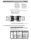
NT31/NT31C side
*2
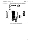
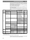
Make the connection between pin numbers 9 and 10 at the terminal NT31/NT31C
(marked
: in the figure above) only.
In order to avoid an FG ground loop, make the connection between the connec-
tor hood and the shielding at one side only.
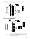
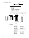
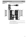
Connection between
NT31/NT31C Units
(RS-422A)