


7-1SectionTroubleshooting
232
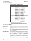
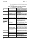
7-1 Troubleshooting
When a fault relating to the operation of the NT31/NT31C occurs, find the symp-
toms in the table below and respond by following the corresponding Remedy in-
dicated in the table.
Note 1. Confirm system safety before turning the power ON/OFF or resetting.
2. Do not disassemble the PT for repair or modification.
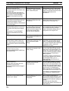
NT31/NT31C Symptoms Cause Remedy
Power LED fails to come
ON
Power is not being supplied. Check the connections and make sure that power is
supplied correctly. (3-1-3 Power Supply Connection,
page 33)
Power supply fuse has blown. Contact your OMRON service center.
Nothing is displayed on
the screen.
Screen No. 0 has been read at the
host side.
This is not an error. Change the screen number
from screen number 0. (Setting the screen number
to 0 turns the screen off.)
The system startup waiting time has
not elapsed yet.
This is not an error. The display will appear after the
waiting time has elapsed.
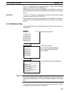
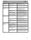
Cannot communicate with
the Support Tool
The Transmit mode has not been
established.
Display the System Menu and select the Transmit
mode. (6-6 Transmitting the Screen Data, page 155)
Spp
Not connected to the Support Tool. Check the installation of the connector cable. (3-2
Connecting to the Support Tool, page 35)
The PT model setting and direct
connection setting at the Support
Tool do not match the NT31/NT31C.
Using the PT Configuration settings of the Support
Tool, set the PT model and direct connection
settings that match the NT31/NT31C.
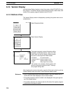
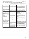
Cannot communicate with
the host
Cannot switch from the
system initializing screen.
Communication error
message is displayed
Memory switch settings do not
match.
Check the communication setting in the Memory
Switch menu of the Maintenance mode, and match
the communication protocol settings for the host and
NT31/NT31C. (6-7 Setting Conditions for
Communications with Host by Using Memory
Switches, page 157)
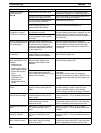
message
i
s
di
sp
l
aye
d
when communicating to
the host.
NT31/NT31C and host are not
correctly connected.
Check that the type, length, and installation of the
connector cable match the specifications. (Section 4
Connecting to the Host from the RS-232C Port, and
Section 5 Connecting to the Host from the
RS-422A/485 Port)
In an RS-422A/485 connection, the
terminator setting is incorrect.
Make the NT31/NT31C and PC termination
resistance settings correctly. (Section 4 Connecting
to the Host from the RS-232C Port, and Section 5
Connecting to the Host from the RS-422A/485 Port)
In an NT Link (1:N) connection, there
is duplication in the unit numbers.
Make the settings again so that there is no
duplication. (6-7-4 Setting the NT Link (1:N) Method
(Standard/High-speed), page 163)
The power to the NT31/NT31C,
NT-AL001 or host is OFF.
Check the power supply.
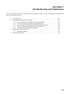
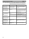
The buzzer has sounded
and the RUN LED is OFF.
Malfunction due to external noise Carry out grounding work in accordance with the
conditions by referring to 3-1-4 Grounding, page 34.
UO
The NT31/NT31 has developed
trouble.
Contact your OMRON service center.
The touch panel does not
respond.
Malfunction due to external noise Carry out grounding work in accordance with the
conditions by referring to 3-1-4 Grounding, page 34.
p
The touch panel is broken. Test the touch panel with I/O Check in the
MAINTENANCE MODE menu. If there is an error,
contact your OMRON service center.
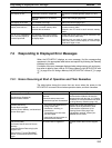
The PC mode has
changed to the monitor
mode.
The NT31/NT31C changes the mode
when host link communication is
used.
This is an NT31/NT31C specification. When using a
PC that can also be connected using the NT Link
method, use an NT Link connection (there is no
mode change with the NT Link method).