


4-1SectionConnecting to the RS-232C Port at the Host
83
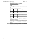
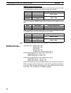
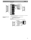
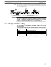
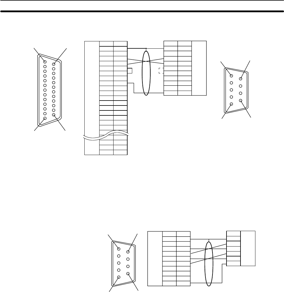
Serial Port B
1
6
5
9
114
13 25
*
NT31/NT31C PC (Host link unit)
FG
CS
RS
RD
SD
TRM
–
–
SG
–
–
SDA (–)
RDA (–)
–
RDB (+)
SDB (+)
–
–
–
RSB (+)
RSA (–)
1
2
3
4
5
6
7
8
9
10
11
12
13
14
15
16
–
23
24
25
–
1
2
3
4
5
6
7
8
9
(9-pin type)
Abbreviation
FG
CS
RS
RD
SD
–
–
SG
–
–
(25-pin type)
Shielding wire
* In case 0V is set for those unit which has CTS setting selector, it is not necessary
to shorten between RS and CS.
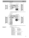
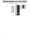
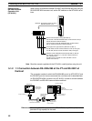
Cables with connectors that can be used at serial port A:
CV500-CN228 (9-pin
⇔25-pin, 2 m)
XW2Z-S002 (9-pin
⇔9-pin, 2 m)
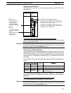
Serial Port A
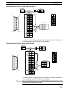
Prepare the adapter cable while referring to the following diagram.
(9-pin type)
Shielding wire
1
6
5
9
Abbreviation
FG
−
SD
RD
RS
CS
+5V
−
−
SG
Pin number
Connector
hood
1
2
3
4
5
6
7
8
9
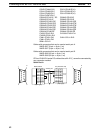
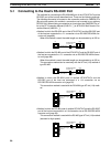
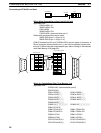
RS-232C
connector
RS-232C
connector
Abbreviation
Connector
hood
SD
RD
RS
CS
SG
NT31/NT31C
PC (Host link unit)
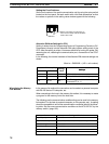
Wiring for a Memory Link
Connection