3-1SectionInstallation
33
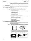
Note 1. During work at the panel, take care to ensure that no metal scraps enter the
unit.
2. The thickness of applicable operation panel is 1.6 mm to 4.8 mm. All fittings
must be tightened uniformly to a torque of 0.5 to 0.6 N⋅m in order to ensure
water- and dust-resistance. Front sheet of NT31/NT31C may be warped if
the tightening is too strong or not uniformity. The panel must not be soiled or
warped, and must be able to support an installation that will remain secure
and strong.
3-1-3 Power Supply Connection
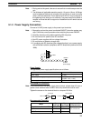
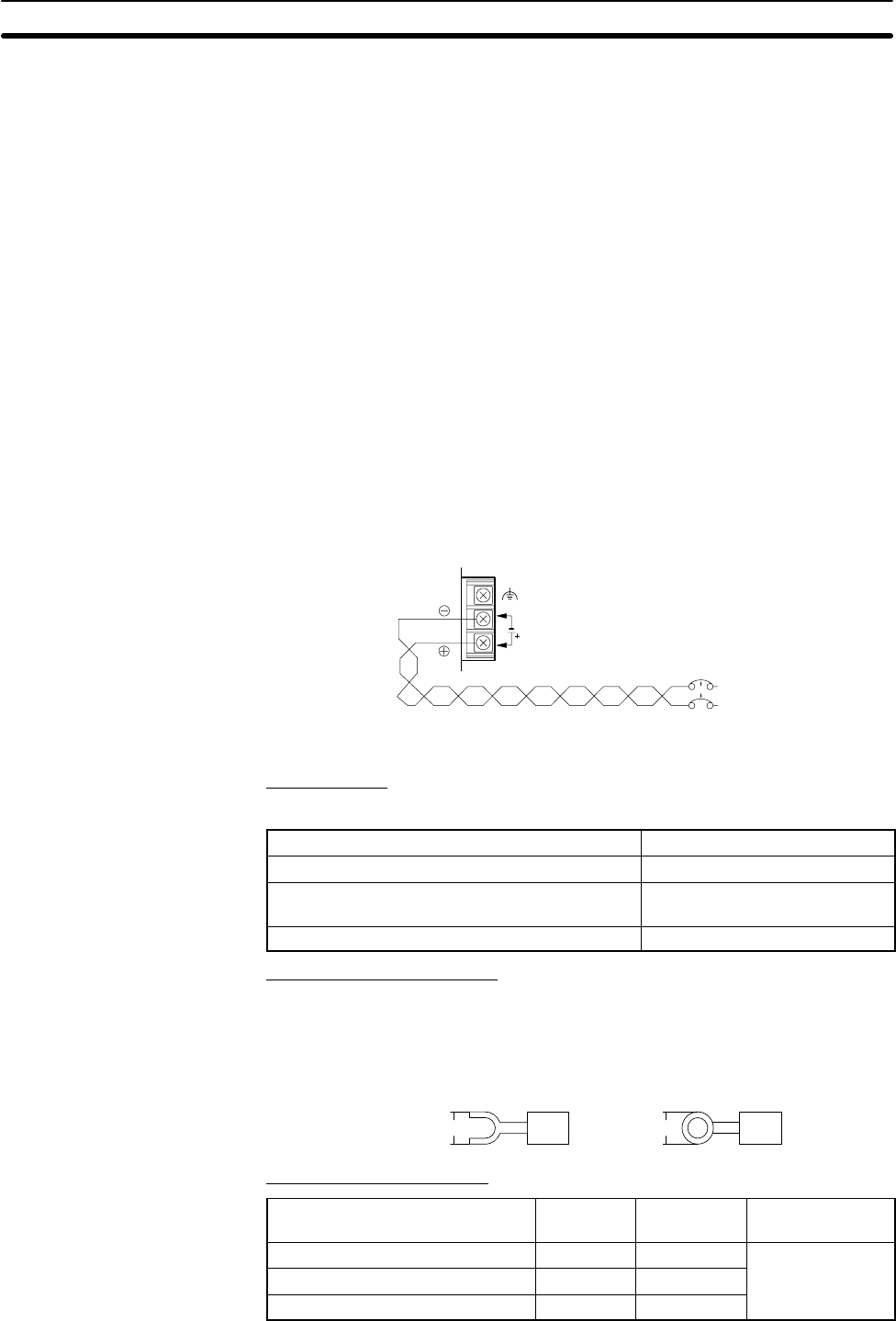
Connect a 24 VDC power supply to the power input terminals.
Note 1. Depending on how the power is switched ON/OFF, the entire system may
stop. Follow the correct procedure when switching the power ON/OFF.
2. Carefully check the wiring before switching ON the power.
3. Do not connect AC power to the DC terminals.
4. Use DC power supplies with low voltage fluctuation.
5. Do not perform a dielectric strength test.
6. If complying with EC directives (low voltage directives), use a power supply
with reinforced insulation (compliance with EC directives is planned for June
1998).
24 VDC
24 VDC
power supply
Breaker
Power Supply
The applicable power supply specifications are as follows.
Item Value
Power supply 24 VDC
Allowable power supply voltage fluctuation range 20.4 VDC to 26.4 VDC
(24 VDC –15%, +10%)
Power supply voltage capacity 15 W or more
Parts Used for Connection
Note For the connection to the power supply terminal block, twisted wires of 2 mm
2
or
greater cross sectional area and M3.5 size crimp terminals must be used.
Tighten the screws on the terminal block to a torque of 0.8 N⋅m.
Fork type Round type
7 mm or less 7 mm or less
Recommended Terminals
Maker
Type
(fork type)
Type
(round type)
Applicable Wire
(stranded wire)
Japan Solderless Terminal MFG 2-YS3A 2-3.5
Fuji Terminal 2-YAS3.5 V2-S3.5
2.0 to 2.63 mm
2
Nichifu Terminal 2Y-3.5 2-3.5


